
![[Building Stargazer Models' Discovery]](kd_disc_Banner.jpg)
By Karl Dodenhoff - images & text © 2011
|
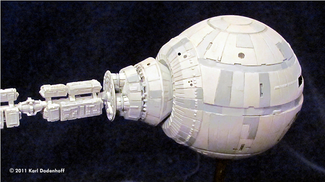
Here's the Stargazer Models rendering of the good ship Discovery One, from the greatest of all classic sci-fi movies, "2001: A Space Odyssey". The assembled model is 30.5" long, very close to 1/144 scale of the Discovery, which was supposed to be 363' long. |
|
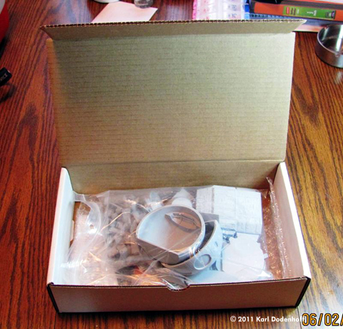
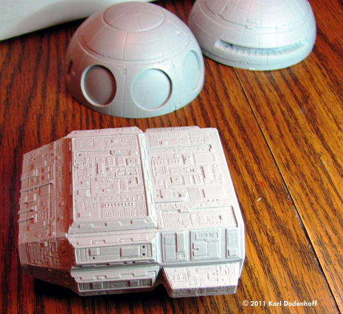
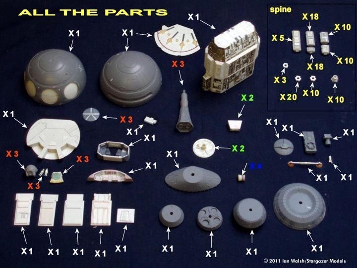
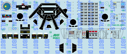
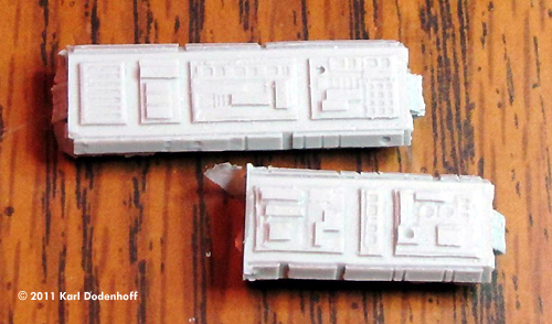
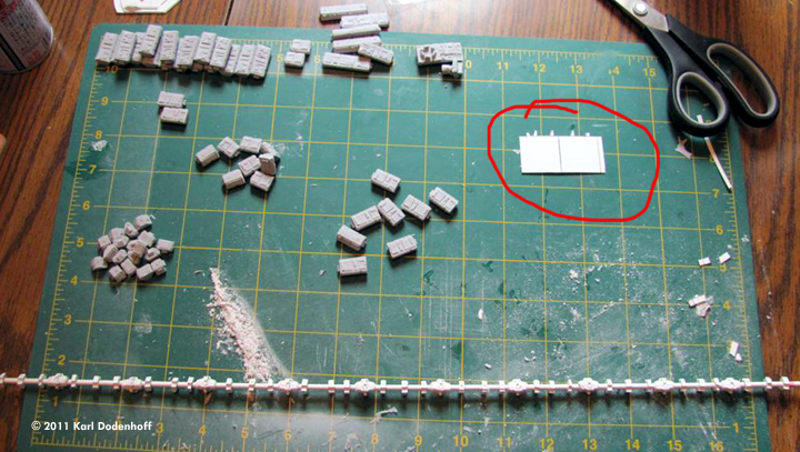
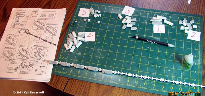
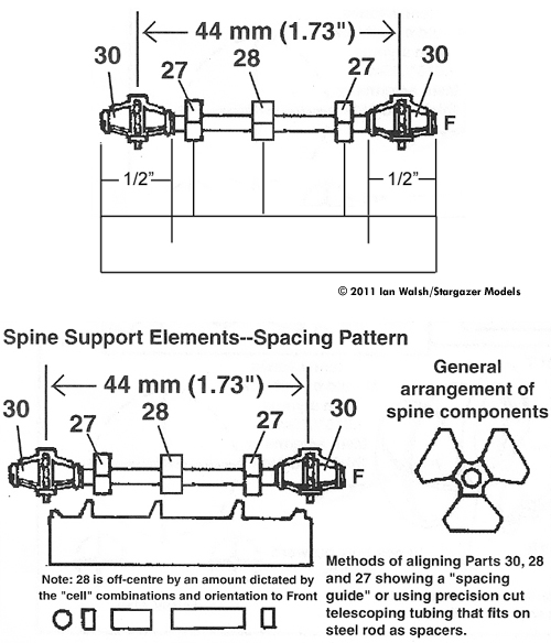
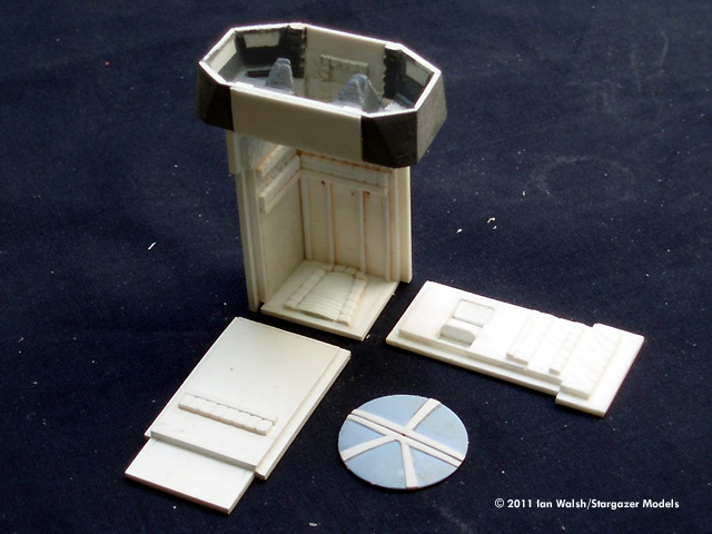
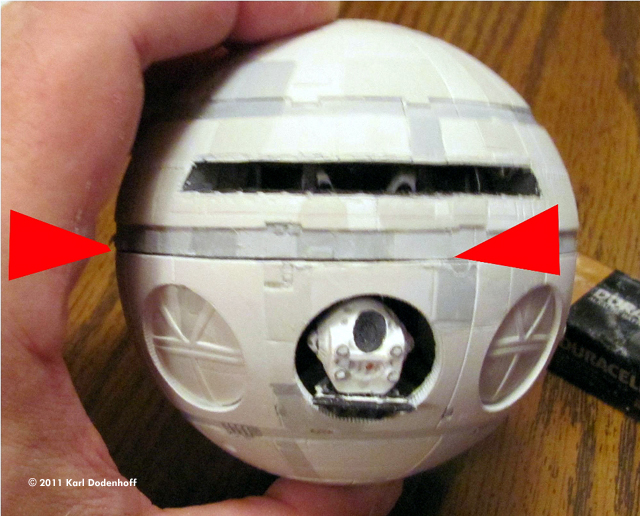
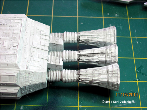
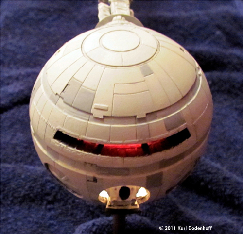
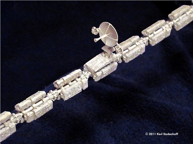
Image: What you see when you open the box Image: The three biggest parts: the hemispheres for the command module and the nuclear engine module Image: All the parts (courtesy of Ian Walsh, with permission) Image: JBot decal sheet The Nuclear Engine Module The Spine Image: Two of the fuel cell podsImage: After gluing the cell mounts and couplings to the brass tube for the spine. Note the template I used for spacing, circled in red Image: Assembling the fuel cell pods on to the spine. Note that they are grouped by number, with the instructions close by. Image: A section from the instructions on assembling the spine Image: A photo from the Stargazer web site, also for assembling the spine The Command Module Image: The bottom surface of the pod bay. The only reason I've included this photo is to show the brass rods used to hold the two pod bay platforms to the left and right of center, and the deployed pod bay with brass rails at center. Image: The completed pod bay inside the bottom hemisphere of the command module Image: The blue space suit seen hanging up in the background on all of the pod bay scenes. It is assumed that this would've been used by one of the survey team members who were murdered by HAL while still in hibernation. It's is there in my pod bay, right where it belongs! Bottle of Testors green enamel paint for scale. Image: The corridor connecting the pod bay to the flight deck, where HAL's "brain room" was located. The rear section of the flight deck is glued to it. Image: A test fit of the hemispheres revealed a fairly large seam between the two halves (seen between the two red arrows). This was filled with putty and sanded down without too much trouble. Painting Image: Post-shading of the nuclear engine module with a dark oil paint washThe Finished Model Image: Another look Image: Another look Image: The spine and main antenna array
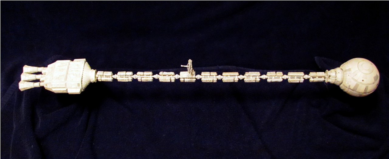
Image: Side view, all 30 ˝ inches. It's very cool having this beauty sitting in front of you once it's completed! |
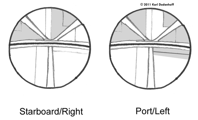
The model is crisply molded in light gray resin, with little flash. Though I forgot to do a parts count at the start of the build, the instructions state that there are over 160 parts, including a piece of clear styrene for the windows (my kit didn't have this, but that wasn't a problem). You are also supplied with a thick sheet of plastic to make the walls of the EVA pod bay (“Open the pod bay doors, Hal”) There is a large sheet of ALPS printed water slide decals by JBot, all of which are for the interior as there are no markings on the spacecraft. When I started building this kit, I found that many of the decals on the sheet were unidentifiable as to where they were supposed to be applied, so I got in touch with both the decal maker and the creator of the model and they helped me out with this. The instructions sheet is 13 pages long and very detailed, except as previously noted for the decals. The model itself poses a few challenges, (as almost all limited run kits do). Most notable of these is building the “spine” e.g. the thin skeletal-looking assembly which connects the nuclear engine section in the back to the spherical command module at the front. Unlike the Lunar Models kit, the spine needs to be assembled piece-by-piece, but for me this is preferable as it makes for a much more detailed assembly. The builder is left to supply their own metal rod to form the core of this assembly. Care must be taken when choosing what to use so that you don't get sagging of the assembly. I bought a 1/8” steel rod at Home Depot but it seemed nowhere near strong enough not to sag. So, I went to my local hobby shop and bought 3 feet of 1/8” brass tubing and 3 feet of slightly smaller tubing to go inside of it. I inserted the smaller tubing into the larger and glued it all together, but I still ended up with a slight sag in the assembly. Someone recommended buying 1/8” brake line tubing at an automobile supply store. This might work but I didn't try it. As with all resin kits, I started out by washing all of the parts in hot water and scrubbing them with Simple Green spray to remove the oily mold release chemicals. I primed the parts with Tamiya white enamel primer paint in a can. I used Zap-A-Gap CA glue for most of the build, and 2 part, 5 minute epoxy wherever I needed an extra strong bond. All paints were Testors enamel. There are 3 main sub-assemblies, with varying amounts of work needed to build each. From back to front they are: the nuclear engine module, the spine, and the spherical command module. The Nuclear Reactor Engine Module By far the simplest assembly to build was the rear nuclear engine module. It is comprised of only 9 parts. The builder is required to drill holes for the 3 engines and for the spine rod to be inserted inside the front of the module. By far the flashiest part was the frustum at the front. There are a series of indentations along the back edge of it and many of these were almost completely filled with resin. So, I sanded the surface against a piece of rough sand paper to remove as much resin as I could, then drilled out all of the holes with a Dremel tool, which took about 2 hours to do. There were also some gaps in the moldings of 2 of the engines, which I filled with strip styrene and sanded down to match the surface. The Spine Next up was the spine. As mentioned before, I formed the core of this assembly with double brass tubing. I then spent several hours figuring out the layout of the modules, of which there are 11 including 1 for the primary antenna array (where Frank Poole took his deadly EVA to replace the AE 135 unit in the film). To build the spine the modeler must make himself thoroughly familiar with the design of it first. This is absolutely critical for the spacing of the couplings between the modules and the “small support elements” to which the pods are attached. The instructions include a drawing of a template one can use to lay it all out. I used this to make a template out of the sheet styrene supplied with the kit (there is plenty of it to spare). Not only must one align these pieces horizontally along the length of the tube, but the surfaces to which the modules will be glued must also be aligned together along the same plane so they all match in order for the modules to be aligned to each other in a straight line. There are 33 parts called “cell mounts” which are hexagonal in shape. They are molded together onto a flat sheet of resin. First you have to sand away the excess resin by running it over a sheet of sandpaper taped to a flat surface. Then, you have to drill out the center of each piece. You also have to drill out the centers of each coupling, of which there are 10. All of this drilling has to be done with a 1/8” bit, to match the diameter of the rod used for the spine. After gluing all of these parts to the brass tubing, I then sorted out the module pieces by number. There are 5 different module parts which form 3 sub-assembly types. It is suggested that you start at either the front or back and work your way down the tubing, methodically building up each assembly as you go. There are 11 groups or modules of cells, numbered in the instructions from back to front, with number 5 being the main antenna mount module. Once I had glued all of the fuel cell modules to the spine, I noticed that some of them were not aligned well, so I pulled them off and either sanded down the facets of the small support elements, or added small pieces of strip styrene for shims as needed. The other part of the spine is the main antenna array. This was fairly easy to build but note that the modeler has to build the feed horns and braces from scratch. There is a nice photo of the full scale movie prop in the instructions to help with this. After I completed it, I left this part off until last in order to prevent it from being broken off while I handled the model during assembly. Command Module Finally we come to the spherical command module at the forward end of the spacecraft. The kit features a very nicely detailed interior for this scale, but unfortunately most of it disappears once it is assembled. The instructions offer a method for building it so that it can be opened later, but I found this to be impossible for reasons that will be explained later. I had always wanted to build a model of the Discovery with a lit interior, even though I've never lit a model before and I am a complete moron when it comes to electrical stuff. I finally decided to take the plunge and give it a go for this model, and the result was awesome! But, I will skip that part as it is beyond the scope of this review. There are 3 main sub-assemblies to the interior: the flight deck, the pod bay, and the corridor connecting the two. All of these have almost complete decal coverage! There is also an option to build the so-called “warehouse” corridor which connects to the pod bay. The largest decal on the sheet is for this purpose. I chose not to build it for the same reason I already noted - it would simply disappear once the sphere halves were glued together. There are also 3 EVA pods, molded in 1 piece. These did not include the “Waldo” arms featured with the pods in the film. At this scale, they would have been incredibly tiny and brittle if molded in resin. I didn't build them for the same reason. I started out by building the pod bay. As is my usual practice, I primed everything with Tamiya white primer paint from a can. The floor of the bay is molded in 1 piece, and is pretty much covered completely by the decals provided. Next, one must build the walls of the bay. I used L-shaped Evergreen bracket glued to the floor to add something to glue the wall panels to. Then you have to measure out each panel, cut it, and glue it into place. You may want to cut the single, big decal for the wall into pieces to match each panel and apply it before you glue it in place. Lastly I painted the control panel that sits in the center of the room and the pods, and glued them into place. I also chose to depict the center pod being deployed out the hatch of the bay. To do this, one must first remove the resin from the circular hatch. Then I cut some square brass tubing to size, drilled holes into the rear of the deployment ramp and the floor panel, and glued it into place partway out the hatch. Next up was the corridor connecting the EVA pod bay to the flight deck. In the movie, this is where David Bowman goes when he disconnects HAL's “brain”. It is a simple affair to assemble, consisting of only 5 resin parts: the 4 walls plus the hatch. There are a couple of decals for this assembly, though it all disappears once the sphere is assembled. Finally I came to the flight deck. Again, this was very simple to assemble, and there are decals for all of the control panels. The 2 chairs on the flight deck are semi-gloss black. Once the EVA pod bay, corridor, and flight deck are glued into place, it's time to assemble the sphere. Here's where I ran into a bit of trouble. The 2 halves of the sphere didn't match up well when I glued them together, and I ended up with a fairly sizable seam along the surface where the two join together. I used Squadron white putty to fill the seam, which wasn't difficult, but the presence of this seam would've been very clearly visible if I had decided not glue the 2 hemispheres together so as to be able to open it and show the interior. Once the sphere is assembled, one must glue in the hatches to the front of the pod bay. 3 of these are supplied, though I only used 2 as the center hatch was open. Each hatch has a different paint scheme, so I spent a bit of time looking at them on my DVD and came up with a drawing. Painting Once the 3 main sub-assemblies are built, it's time to paint. I used matt gray and white to make a very light gray color, then painted the entire spacecraft with it. Then, I added a little more black to this mix to make a slightly darker shade, and painted several panels on the sphere and the nuclear reactor unit with this color. I continued in this manner, using photos from the internet and screen captures I did on my laptop from the DVD as references. Care must be taken to go easy with this - some of the variations in the shading are very subtle - don't overdo it! Lastly, I made a thin wash of black oil paint and brushed it into the recessed panel lines and lower surfaces all over the model. After this dried, I cleaned it up by dry brushing the original colors in areas where the oil paint wash got onto the upper surfaces. Finally I used the original light gray enamel mix I'd previously painted the entire spacecraft with, and lightened it with some white paint. I then picked out some of the raised areas on all of the parts by dry brushing this on. Doing this is slow, tedious work but I felt it was well worth the effort to get the surface details to “pop”. Otherwise, the Discovery will look very bland. Once the paint had dried, I finally glued the main antenna array in place on the spine. Once assembled, the builder really should consider mounting it in some manner. Otherwise, it just looks wrong lying there on a table or shelf! I used brass rod inserted into holes I drilled into the bottom of the front and rear modules, then mounted these into a piece of wood. If you get any sag in the spine (mine did, slightly) you may wish to brace it up with one or two more pieces of brass rod (or whatever you choose to mount it with). Conclusion I started this model in May of this year and completed it the week after Thanksgiving, which is about the normal amount of time I spend on a sci-fi model of this size. As I said earlier, it is not without its' problems but these are not outside what one would expect from a limited run resin kit. Having said that, I would not recommend this to someone who doesn't have a moderate amount of experience with this media and this type of kit. It's not for beginners. Once completed, it is truly a joy for someone like me, who saw this movie in its' first run in a movie theater in my youth, and has had an on-going love affair with the subject ever since. FYI I already have the Moebius Models new release of The Moonbus purchased and waiting in the wings for me to build! |
![]()
This page copyright © 2011 Starship Modeler™. First posted on 24 March 2011.
![[Please click to enlarge]](kd_disc_Fig03.jpg)
![[Please click to enlarge]](kd_disc_Fig04.jpg)
![[Please click to enlarge]](kd_disc_Fig08.jpg)
![[Please click to enlarge]](kd_disc_Fig09.jpg)
![[Please click to enlarge]](kd_disc_Fig13.jpg)
![[Please click to enlarge]](kd_disc_Fig16.jpg)
![[Please click to enlarge]](kd_disc_Fig19.jpg)
![[Please click to enlarge]](kd_disc_Fig21.jpg)
![[Please click to enlarge]](kd_disc_Fig23.jpg)
![[Please click to enlarge]](kd_disc_Fig24.jpg)