
|
By B.P. Taylor - images & text © 2006
If the announced national goal of the United States is to return astronauts to the moon as a component of a broader policy of space exploration, part of that goal will entail the development of spacecraft capable of not only getting us there, but maintaining our presence as well. According to many space experts, the most likely impetus for a return to the moon and establishing permanent bases will be tourism and scientific research. Lunar bases could be used to test advanced space technologies with an eye toward other destinations. Of course, a vehicle would be required to ferry equipment and provisions to the inhabitants of any lunar base, and it is that idea that became the subject of my next model project. |
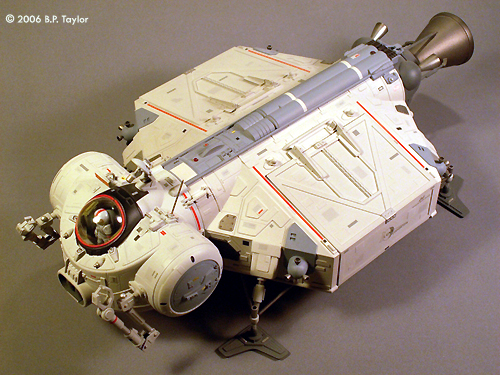
![[Please click to enlarge]](btcs/bt_cshuttle_A.jpg) The Luna Corporation Cargo Shuttle arrives at Farside Base with equipment and provisions for the inhabitants of this underground research facility. Using a remote manipulator system and magnetic attachments, freight containers are removed from the shuttle's cargo bay and deposited near the airlock doors. |
|
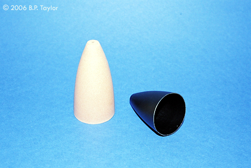
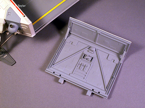
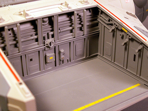
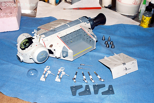
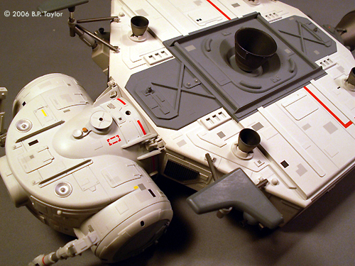
Image:1 The lander component and work pod were built around a 2-inch diameter EMA/Plastruct tube. Sixteenth inch acrylic sheet was then used to build up the basic shape. Image: The workpod was an assemblage of EMA/Plastruct tubes and tube sections. A separate interior was constructed and painted, then glued into the main tube before being capped off with elliptical vessel heads. Image: The main engine bell was vacuformed over a Renshape lathe-turning. Image: The cargo bay was detailed primarily with Evergreen structural shapes. Image: Interior detail on Cargo Bay door.
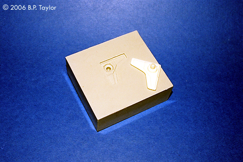
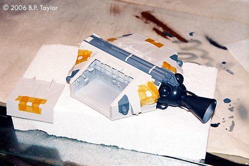
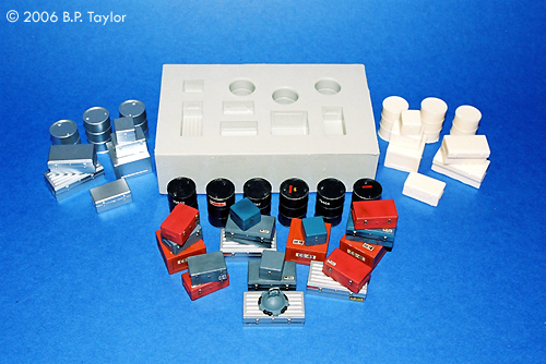
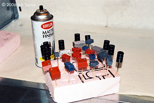
Image:8 Various areas are masked off in preparation for airbrushing contrasting colors. Nichiban, a low-tack rice paper tape, is used in most cases, and in conjunction with masking fluid. Image: Beginning with ABS and styrene masters (left, in silver), an RTV mold (center) was made into which urethane resin was poured, resulting in the raw castings shown (at right). Multiple castings of this mold gave me plenty to load into the cargo bay and stack up on the landing pad. They were painted various colors and weathered a bit with pastels and dry-brushing. Image: Containers were airbrushed in various colors, then dirtied up a bit with pastels and dry-brushing.
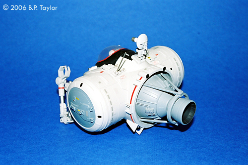
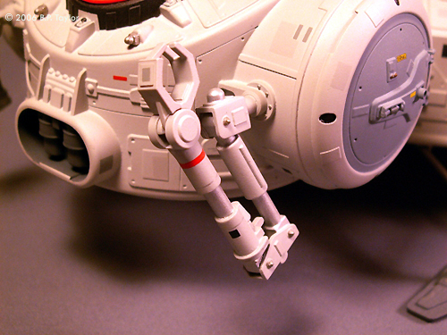
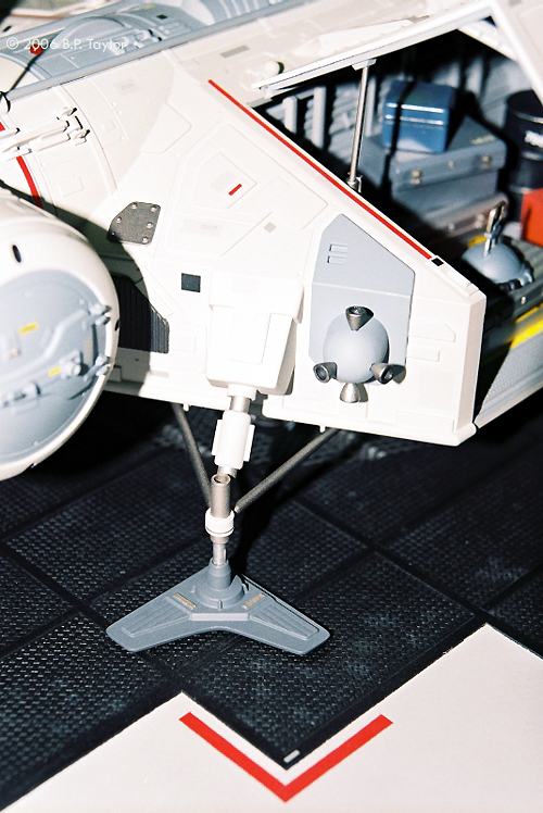
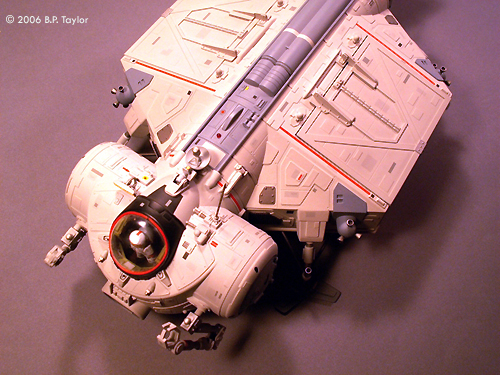
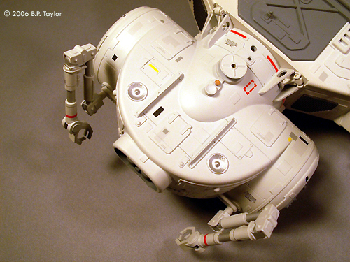
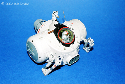
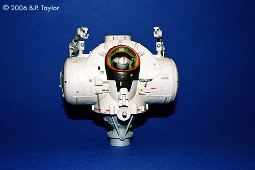
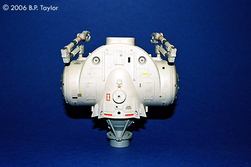
Image: In this close-up of the completed workpod, engine details can be seen at its rear. Image: Landing gear struts are attached. Image: The workpod is designed to separate from the lander component and also provides access to batteries and a circuit board that drives LED flashers. Image: Close-up of manipulator arms and hatch detail. In "reality," access to the workpod interior would be through hatches at either end of the main tube and would provide the pilot with enough internal space and provisions to operate independently for several days.
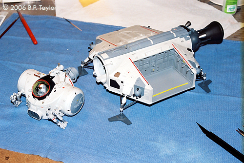
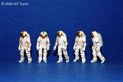
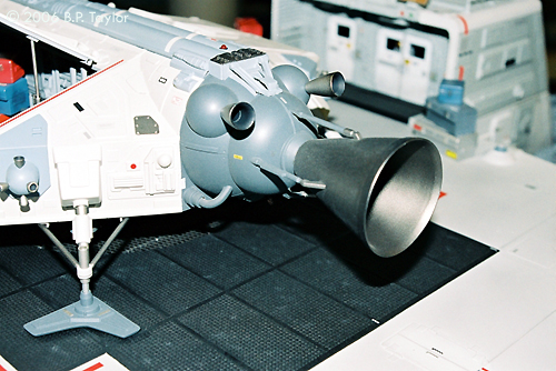
Image: Close-up of Hatch detail. Image:18 One side of the lander was built up so that an open cargo bay could be shown. The door can be displayed either closed or propped open and loaded with resin-cast freight containers. Image:19 The landing gear were created from soldered brass tubing and styrene with resin-cast footpads. Also visible are one of the thruster quads, which utilize nozzles from a 1/32nd scale lunar module kit. Image:20 Astronaut figures were resin castings that were removed from the mold while still "green" (soft). This allowed me to reposition arms and legs a bit to get a little variety in their poses. A steel pin was inserted into holes drilled into their legs so that I could use magnets beneath the landing pad to hold them in place instead of gluing them.
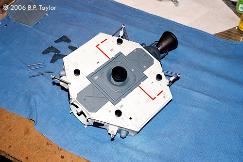
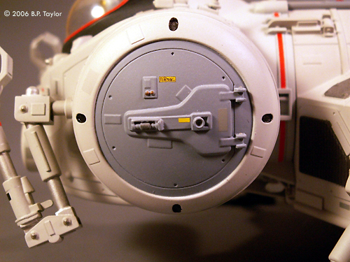
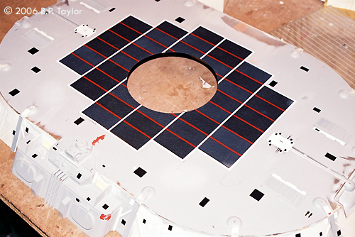
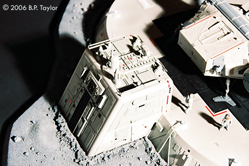
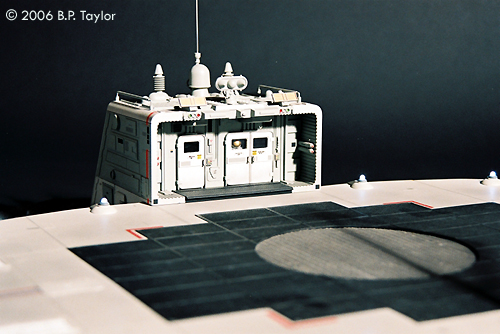
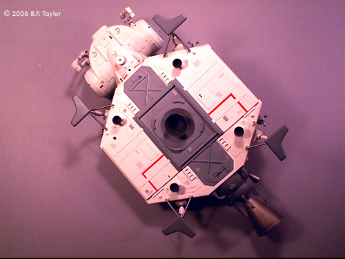
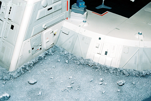
Image: The central opening in the landing pad will be covered by a blast grating and is surrounded by resin-cast tread plate panels to give the surface more of an industrial look. Image: Detail of airlock structure. Image: Inset area of airlock structure showing door detail. Graphic on one of the doors states "Guard dogs on duty." Image: Rear engine detail on lander component.
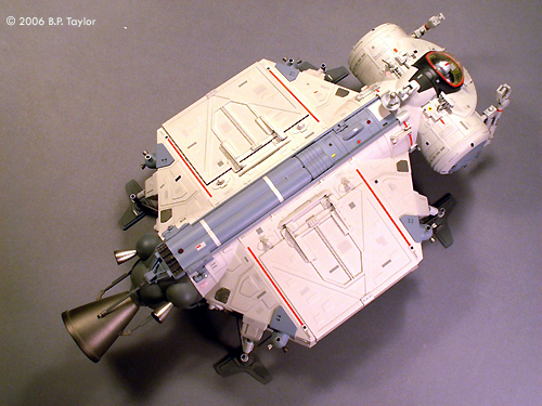
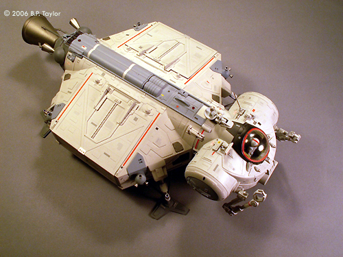
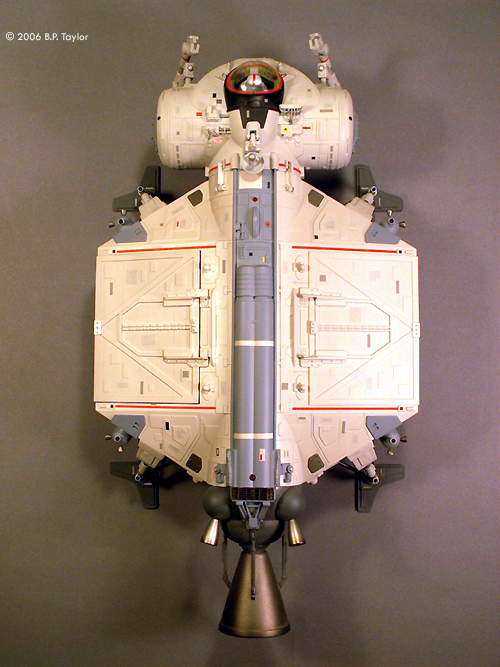
Image: Additional view of completed Cargo Shuttle. Image: Additional view of completed Cargo Shuttle. Image: View of Cargo Shuttle underside. Image: Another view of Cargo Shuttle underside.
Image: The completed workpod with hand-painted details and graphics, some of which are too small to be seen here. Image: Top view of completed Cargo Shuttle. Image: Top view of workpod. Image: Bottom view of workpod.
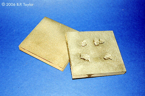
Image: Test panels for the surrounding terrain were made using Glaze Coat and Woodland Scenics fine ballast. These panels were also used to try out different painting techniques such as washes and dry-brushing. Image: To give the impression that the terrain had been disturbed as a result of site preparations, I mixed up a slurry of Glaze Coat and ballast, then formed it around the landing pad with sculpting tools.
|
I envisioned a scenario that would begin with the launch from Earth of an unmanned cargo rocket, resulting in its upper stage freight container in low-Earth orbit. Awaiting this container would be the Luna Corporation Cargo Shuttle which would slowly catch up to it, matching orbital characteristics with bursts from its OMS and thrusters. Maneuvering next to the now open freight container, the front section, or work pod, would detach from its lander component and, using its manipulator arms and magnetic attachments, carefully arrange each item in the cargo bays. With transfer complete, the work pod would once again hook up with the lander component and, with the cargo bays fully loaded and secured, fire its main engine, sending it on its way back to the moon. Now that I had a basic concept, I needed only a few simple drawings to get me started, just to establish general proportions and such. For me to do elaborate design drawings is usually a waste of time because once I begin working in three dimensions, things start to deviate anyway. I decided that I would construct the Luna Corporation Cargo Shuttle in 1/48th scale, which if I didn't stray too much from my basic layout, would result in a model about 12 inches long. LANDER COMPONENT I began with the lander component which I built around a 2 inch diameter length of EMA/Plastruct tubing. 1/16th inch acrylic sheet was then used to build up the basic shape. Starting with a bottom plate onto which the tube was fixed, I used the "scribe and snap" method to create the various walls and facets. Any gaps were filled with Evercoat Polyester Glazing Putty and sanded smooth. Once I was satisfied with this, I could begin adding a bit of surface detailing, which I accomplished with scribed lines and various thicknesses of Evergreen sheet and strip. A modified Saturn 1B part from the "Man in Space" kit was applied to the main tube and an EMA/Plastruct hemisphere was glued to the rear. I had determined early on that it would be much more interesting to show one of the cargo bay doors in the open position, allowing me the opportunity to detail the inside walls of the bay. This was done almost entirely with Evergreen structural shapes and piping runs. The open cargo bay door was built from thin styrene sheet and detailed with more Evergreen strips. Unfortunately, the thinness of the plastic and the action of the plastic solvent as I applied the various details resulted in a door that had a bit of a warp to it. I was, however, able to correct this by gluing a length of square brass tubing to the inner edge which straightened it out. The door can be propped open with two simulated "hydraulic arms" made of brass tubing and styrene, or can be displayed in the closed position. Of course, now that I had a cargo bay, I would have to create an assortment of shipping containers to place within it. The crates and equipment boxes were initially machined in various sizes from ABS and detailed with styrene and pieces borrowed from tank kits. 1/35th scale drums were used as is, since they wouldn't appear too much out of scale with the other shipping containers. Tiny latches and hinges were very carefully razor-sawed off the tanks and applied to the ABS boxes with plastic solvent. A coat of primer followed, and then the completed crates, boxes, and drums were tacked down as a group to a plate of ABS. Plastic walls were built up around them and RTV was poured into the resulting cavity. When the mold was ready, urethane resin was poured into the mold, a waxed plexiglas plate was layed on top and the parts were left to cure. Multiple castings were made of this mold to obtain sufficient numbers of shipping containers, which were then painted various colors and weathered a bit with pastel chalks and a little drybrushing. The main engine bell was vacuformed over a Renshape lathe-turning and the two smaller OMS (Orbital Maneuvering System) nozzles were urethane castings that were plugged into 3/4 inch diameter EMA/Plastruct hemispheres. Brass tubing was used for the landing gear struts and was soldered together with a micro-torch while the pieces were held at the proper angle in a simple jig. These were done longer than needed, then cut down to size after soldering. Sections of styrene tubing were then slid onto the brass struts to visually beef them up a bit. After arriving at a footpad shape that I liked, I made a single master from acrylic sheet, molded it in RTV and cast them up in quick- setting urethane resin. The landing leg supports were also urethane castings from a single master. The RCS (Reaction Control System) was comprised of urethane castings that were drilled out on a milling machine to accept nozzles taken from a 1/32nd scale lunar module kit. A final bit of detailing was added in the form of adhesive vinyl panels. Various rectilinear shapes were cut out with a sharp X-acto knife and straightedge, and then these were randomly applied all over the lander component. (This would also be repeated on the work pod.) Layers of paint would seal these on permanently. WORK POD I drew inspiration for the front section of the Cargo Shuttle from both the classic Bottle Suit (from the mid-1950's Disney/von Braun TV collaboration "Man in Space") and the Space Pod from 2001: A Space Odyssey, which itself was a direct descendant of the Bottle Suit. This work pod, although designed primarily as a cargo transfer vehicle, could also be used in a number of different capacities--as a tug, in construction of large scale space structures or performing maintenance tasks. The work pod was an assemblage of five different diameter EMA/Plastruct tubes and tube sections, all blended together with Evercoat, then lightly sprayed with gray automotive primer. I built an interior for the pod as a separate unit from sheet styrene and urethane castings, painted the completed assembly, and slid it into the main tube, closing it up with an EMA/Plastruct elliptical vessel head. Next, I began sketching lightly on the primed surfaces in pencil to establish where I would apply details such as scribe lines, paneling and the like, drawing again on an assortment of Evergreen strips and sheets, as well as a few select kit parts and urethane castings to jazz it up a bit. A moveable antenna was constructed of various odds and ends, and then glued in place behind the clear canopy which, like the Bottle Suit, was incorporated into the design to give the standing pilot plenty of visibility. For the clear bubble, I couldn't rely on any found object, so I vacuformed one myself out of .020 clear PETG, a styrene-like plastic that forms easily. I pulled the PETG over a polished acrylic lathe-turning, which gave me a nice clear part. In the final assembly, the bubble would be one of the last parts attached. I also added engine details to the rear to further reinforce the idea that the work pod is capable of operating independently, although obviously, this is only visible when the two components are separated. The manipulator arms were easily fabricated from various Evergreen styrene tubes and channels, while the grippers were cannibalized from a Gundam kit I had lying around. Grandt Line nuts, bolts, and rivets were then applied to suggest pivot points. FINISHING THE CARGO SHUTTLE With all of the detailing completed, I gave all of the miscellaneous components a unifying coat of gray automotive primer, and then inspected each one for any minor flaws. Application of Nitro-Stan putty took care of these and after a final going-over with 600 grit wet or dry and another light coat of primer, I laid down a basecoat of light gray. Once the basecoat was dry (which doesn't take long when you're using lacquers), I began masking off certain sections with a combination of tape and masking fluid, then airbrushed a number of grays, blue-grays, and metallics, with black sprayed around the bubble canopy. Many tiny graphics (some that are too small to pick up in photos) were applied to the model--some in the form of decals, while others were custom-made dry transfers. These were all sealed on with a couple of coats of clear matte lacquer. Finally, handpainted details were added with enamels and a 10/0 brush. With painting completed, it was now time for the assembly phase which, thanks to prior planning and test-fitting of components, was a simple matter. Epoxy was used for everything but the clear bubble, which was fixed in place with R/C-56, a vinyl glue specifically made to attach clear canopies on radio-controlled aircraft models. The manipulator arms were epoxied "elbows-out" as it seemed more interesting than having them hang straight down and does seem to give it a little more "personality." The final touch was applying a "seal" around the bubble canopy which was done with a length of fine gauge red electrical wire. In addition to providing a nice color accent, this wire tends to help draw your eye to the bubble, beneath which the pilot can be seen at his controls. LANDING PAD The Luna Corporation Cargo Shuttle was now completed, but it lacked a destination, and this got me thinking of how I might best display it. The obvious solution was to build a landing pad and surrounding lunar terrain. After a few sketches, what I arrived at was similar to the landing pads seen in "Space:1999," although mine is decidedly more low-tech -- no extendable docking arm or elevator platform -- but I did include landing lights and a cargo loading arm modeled very closely on the Space Shuttle's Remote Manipulator arm. Beginning with the pad, I created a basic structure using MDF which was then sheeted in 1/16th inch acrylic and vacuformed ABS wall sections. Adjoining structures were built out of acrylic sheet and everything was detailed with styrene and kit parts, as well as pieces from a surgical stapler and short lengths of guitar string. Single and double doors were applied to the inset area, and then the window areas were masked off so they would remain clear after painting. The central opening in the pad would serve as a blast deflector, channeling exhaust through a grating and out two side ports. The grating began with a machined ABS ring onto which a fine aluminum mesh was applied. Styrene ribs were then added to the underside to suggest structural members. The area surrounding the blast grating was covered in tread plate panels cast from an RTV mold. Once I had enough of these castings, I spray-mounted them (tread plate down) to MDF and gradually fly-cut them down on a milling machine to a more scale-like thickness of fifteen-thousandths of an inch. They were then carefully aligned and glued to the acrylic substrate with CA. Styrene strips and pin-striping tape were also used in this area. Bezels for the landing lights were cast up from yet another RTV mold, then were drilled out to accept T-1 LEDs before being glued down. As on the Cargo Shuttle, the last bit of detail was in the form of randomly applied adhesive vinyl panels. Once I was satisfied with the detailing, I went through the usual finishing process -- primer, application of spot putty, followed by another shot of primer. I then painted the entire landing pad and structures using basically the same color palette that was used on the Cargo Shuttle. The tread plate area was painted black to provide a little contrast. Finally, graphics were applied and clear-coated with a matte finish. The only weathering I really felt was warranted was to dirty the top surface of the pad and around the perimeter at ground level. This was done by applying pastel powders with a large duster, then burnishing them into the matte finish with a towel. Another light coat of matte lacquer sealed this on and prevented the pastels from smudging and picking up finger prints. LUNAR TERRAIN Moving on to the surrounding terrain, I band-sawed and routed a 3/4 inch sheet of MDF, then cut an opening in the center of it so that once the landing pad was secured to it with wood screws, I would still have access to the underside for wiring and assembly. Various sized hole saws were used in a drill press to create locations for the craters. The dish-shaped depressions were then done with filler, but rather than sculpt each one of these by hand, I decided to use several different sized EMA/Plastruct plastic domes and mold them in. |
|
After applying release agent to the domes, I proceeded to fill up each hole completely with Evercoat, then pushed a dome into the putty until it met the top edge of the hole. After the putty had gelled, I popped the domes off, removed excess filler, and softened the resultant crater rims with coarse sandpaper. Slight rises in the terrain were random shapes sculpted from chunks of floral foam and stuck down to the MDF. They were then coated with several layers of quick-setting urethane resin to create a hard shell, and blended into the surrounding terrain with more Evercoat. The routed edge of the MDF base was going to be left smooth, so it was sealed, then sprayed with K-36 ( a catalyzed urethane primer), sanded down to 400 grit wet or dry and painted a dark gray. When this was completely dry, I very heavily masked off this edge in anticipation of the next step, which was to coat the surface with a product called Glaze Coat, a high-build epoxy coating. Before doing so, I placed the landing pad on the base and traced around it with a pencil to define the area that needed to be done. Having previously done some test panels using different Woodland Scenics ballast, I mixed up a single batch of Glaze Coat and spread it around and up to the masked-off edge. The test panels showed me that I had plenty of working time, so I wouldn't need to rush. I then sifted the fine ballast into the wet epoxy coating, completely covering the defined area and allowing it to soak up the Glaze Coat. I continued sifting ballast beyond the saturation point, all the while making a mess of my workshop floor, despite the fact that I'd laid out lots of newspaper. The next evening, I carefully inverted the base, and any ballast not embedded in the epoxy fell to the floor where it was gathered up for re-use. At this point, the Glaze Coat was actually in a gelled state, so I took advantage of this by taking a spatula and cleaning up the masked edge a bit, as well as along the pencil line that defined the landing pad. I wanted to give the impression that the terrain around the landing pad had been disturbed as a result of site preparations, so I decided to pile up lunar regolith ( that's dirt for you terrestrials) around the entire structure. I mixed up a "slurry" of Glaze Coat and some of the reclaimed ballast, and using various sculpting tools, formed the clumpy mess (which looked like something scooped out of the cat's litter box) around and up to the pencil line. As a final touch, miscellaneous rocks were individually glued to the terrain, and when everything was completely dry, the entire base was painted a suitably lunar gray. This was followed by a black wash and finally dry-brushing with a light gray which really did wonders in bringing out the contours and textures of the terrain. With removal of the masking around the edge and screwing on the landing pad components, the only task remaining was to install the landing lights, which as I mentioned before, were T-1 LEDs. Twelve of these were required, along with appropriate resistors, and power was supplied by a set of batteries mounted beneath the landing pad. I finally finished wiring it up at 12:30 A.M., the morning my son, Evan, and I drove down to Louisville, Kentucky for Wonderfest 2004. Now that's cutting it a little too close. CONCLUSION And there you have it. The entire project was completed within a year in my spare time and entailed many late nights (especially toward the end), but the final result was well worth the effort that went into it. The Luna Corporation Cargo Shuttle was my entry in the Model Contest at Wonderfest 2004 and I was extremely proud when it was recognized with one of two Gold Awards handed out in the Vehicle/Mecha category. Hopefully, the scene depicted here will become a routine event. With a little political foresight and renewed public interest, we may one day get back to the moon and establish a permanent human presence there, but until the real hardware is actually designed and built, it's a lot of fun to speculate as to the forms that these vehicles might take. I enjoyed putting together this article and hope that something contained in it will help you in your modeling endeavors. Thanks to Chuck Emmons for advice on the electronics. |
![]()
This page copyright © 2006 Starship Modeler™. First posted on 8 February 2006.
![[Please click to enlarge]](btcs/bt_cshuttle_B.jpg)
![[Please click to enlarge]](btcs/bt_cshuttle_C.jpg)
![[Please click to enlarge]](btcs/bt_cshuttle_D.jpg)
![[Please click to enlarge]](btcs/bt_cshuttle_E.jpg)
![[Please click to enlarge]](btcs/bt_cshuttle_F.jpg)
![[Please click to enlarge]](btcs/bt_cshuttle_G.jpg)
![[Please click to enlarge]](btcs/bt_cshuttle_H.jpg)
![[Please click to enlarge]](btcs/bt_cshuttle_I.jpg)
![[Please click to enlarge]](btcs/bt_cshuttle_J.jpg)