
By Darren Bertrand - images & text © 2007
|
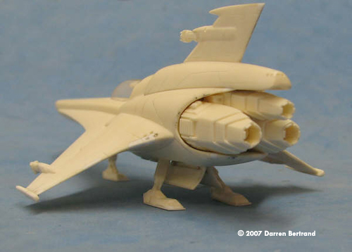
![[Please click to enlarge]](db_mk7_CompletedViperFrontQuarter.jpg) The Viper Mark VII is the state of the art fighter of the Colonial Fleet. It is sleeker and more modern than the Viper Mark II I've purchased every release from Alex and thought that he reached his best with the Viper Mk II model. He proved me wrong. Though mine was a test model, it came fully packaged. Everything arrived in good condition. I immediately took the kit to my workshop, washed the parts, and dove right in. Assembly As with the MK II, breaking the kit into subassemblies greatly simplifies subsequent work and finishing. |
|
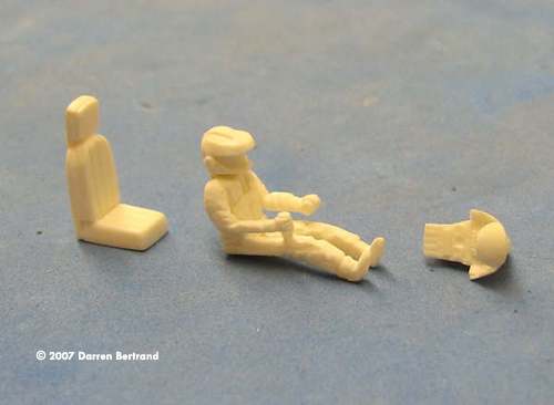
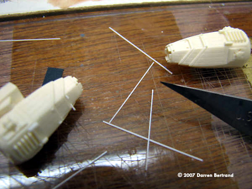
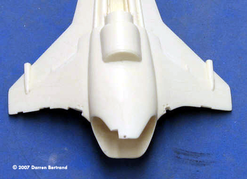
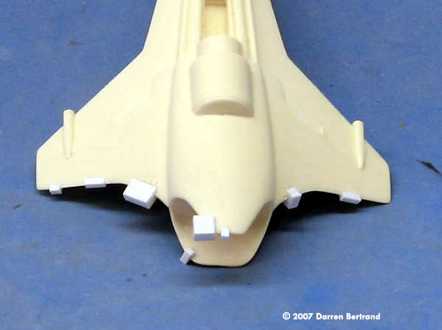
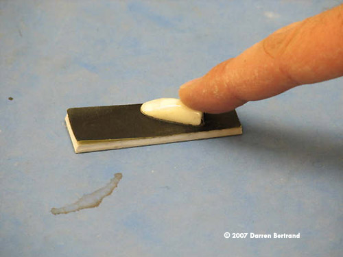
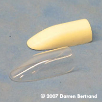
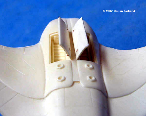
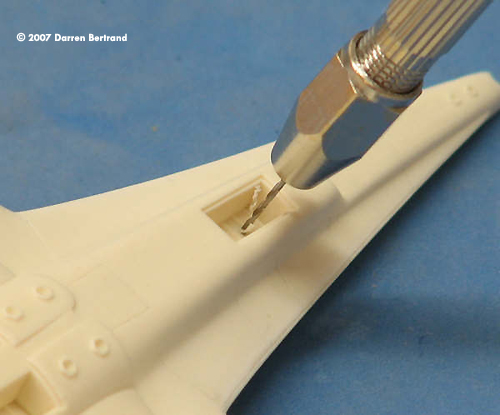
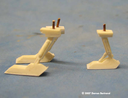
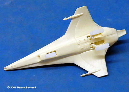
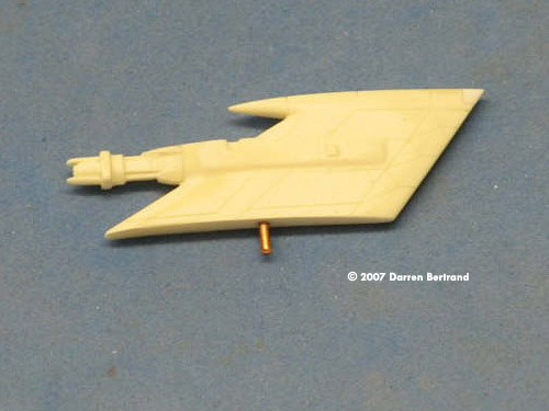
Image: Cockpit parts and nicely done pilot Image: Engine parts Image: Cutting out the bubbles Image: Plastic bits are inserted as filler.... Image: ... and then sanded to shape Image: Sanding the canopy Image: Done Image: Test fitting the main gear covers Image: Drilling out holes for the gear pins Image: Landing gear, pinned Image: Test fit Image: Tail fin with pin Image: Completed engine block Image: Scribing Panel lines Image: Wing detail Image: Rear view |
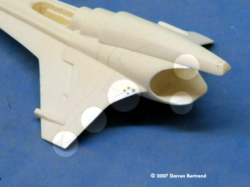
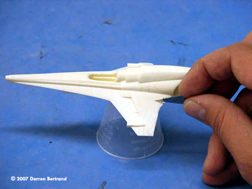
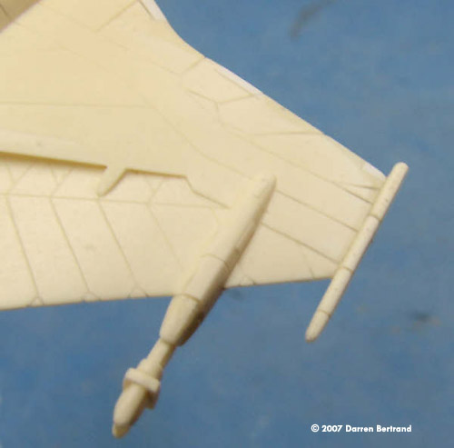
This process was even easier with the MK VII one piece body which was beautifully mastered - right down to the exquisite panel lines. Parts were cleaned of flash as I went along. This was an easy process as the kit is well cast with the exception of the leading and trailing edges of the wings. There were some pretty nasty mold lines which marred panel detail in this area. I found that as I repaired these areas, I needed to repeatedly rescribe the panel lines so as not to lose them. I used a 0.1 mm tri-tool to recreate the fine lines. I did not possess the e-mailed instructions at the time (first run kit); but once I received them, I found that my process did not vary much from Alex's suggestions. Parts were glued in place with super glue which was also used to fill in any gaps. Subassemblies included: the main body, cockpit parts, pilot, helmet, canopy, central engine, main engine block, landing struts, and rear landing bay covers. I chose to attach the central engine cover, top fin, all guns, wing tips and the front landing bay covers to the main body as there was no reason not to - though I left off the rear LG covers to ease fitting the landing gear after painting. I placed a pair of copper pins in each bay cover and drilled corresponding holes in the body. This allowed me to test fit and adjust placement when it is easy rather than after painting - which can be tedious. The same process was used for the landing gear and main engine block. I wanted to leave these as separate subassemblies to ease painting but I also wanted to be able to simply slip them into place when the time came. The landing gear pieces have a boxy base which is intended to fit into the gear bays. This base needs minor sanding to align the gear. The e-mailed instructions have a line guide that should be followed. First, I placed the gear into the bays and marked pin placement. Second, I removed the gear, drilled pin holes, and placed mounting pins. My parts suffered from resin frothing and pin holes and required clean-up. I also removed and replaced the pock-marked pads at the bottom of the gear with new ones built from sheet styrene. Sometimes it's easier to simply replace a whole section rather than wrestle with bubbles and pin holes. It was a shame that I could not hollow out the landing gear struts for accuracy as the rear struts were very brittle. This brittleness worried me so I simple broke the parts in two at the weak point, used a pin vise to drill through the vertical center of the gears, and inserted a brass rod for strength. In all, I found the struts to be the weakest casting of the kit. I was never able to fully regain lost detail and square corners. The vacuum-formed canopy needs to be trimmed for a proper fit. The kit comes with a blank that should be used for this purpose. I placed the canopy over the blank and sanded away the excess plastic - being careful to keep the two pieces tightly together. Sand until the edges of both pieces align. The blank does not reflect the rear bottom fillets of the cockpit and I had to shape these “free-hand.” This is not hard if you take your time sanding and test fit often. Nothing is provided for the canopy frame and this will have to be painted on - after the canopy is tinted to match the CG images. It is at this time that you should test fit the seat, pilot and console. The accurate new pilot figure - as mastered by Bobby Wong - is a welcome change from the MK II pilot. However, it does not fit into the cockpit low enough to clear the canopy. The bottom of the seat, the pilot's rear and bottom of each arm must be sanded until a proper fit is maintained. Test fit with canopy often! I never got the pilot low enough in the cockpit but was able to achieve the 1 mm gap that is suggested by the instructions. I set aside the pilot, helmet, seat, and HUD console as subassemblies for painting. |
|
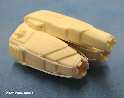
Super-detailing the Engine Block The engine block is the easiest assembly of the kit. One simply glues the top center engine to the main piece and the subassembly is complete. This slides onto the main body very well. If needed, trim the engine block for perfect fit. Now if you're like me and want detail, detail, detail; you are going to want to construct the vector control vanes at the sides of the main engines. This is a difficult job as the detail is tiny. The vanes are also square lengths rather than tubes so forget about using wire. I was simply not able to find length small enough in either styrene or brass, so I ended up making my own. I got some Plastruct lengths at 0.01 x 0.02 and sliced them in half length-wise using a razor blade. I don't recommend this as the process is tedious and lengths of 0.01 x 0.01 are available from Plastruct - though no one in town was carrying any. In order to firmly attach the strips to the engines, drill 0.01 holes at the vane actuators (the short length of rod at the sides of the engines,) and where the vanes attach to the sides of the verniers. As you might have guessed, this involved cutting the main engine block in half to reach the inside faces of the engines. However, with these holes, you can firmly insert the plastic strips and even bend them to the correct angles. Attach the two forward struts first, trim to size, and then attach a long strip at the rear most point and bend the strip to the correct angle. Working forward, glue the long piece to each strut. Finally trim and insert the long piece front into the vane actuators. This is tedious work but the result is worth it. I went one step farther and removed the cast rod/hoses at the front of the vane actuators and will place wire once painting is complete. Now onto painting… The included decals by JBOTwere simply too fragile. I had several disintegrate while sliding off the backing paper They are detailed (down to pilot badges and HUD screens) and good quality. The alternative battlestar markings are good, but the limited (TV main characters) pilot call-signs are not. Alternate registry numbers would have also been appreciated. Overall You can't get better than this for a small MK VII Viper. Well worth the price! |
An update to this article from Federation Models:
|
![]()
This page copyright © 2007 Starship Modeler™. First posted on 14 August 2007 . Last updated 22 August 2007
![[Please click to enlarge]](db_mk7_KitContents.jpg)
![[Please click to enlarge]](db_mk7_Pilot-CanopyTestFit.jpg)