
|
By Tony Celliers - images & text © 2008 As a child I really enjoyed Battlestar Galactica, and found the spaceships intriguing to say the least. Particularly the Colonial Viper, recently called the Viper MK1. Of course I was disappointed when the show was cancelled, and at the time had no idea that it would take a whopping 15 years to resurrect, which it did in a big way. Not only were some of the characters sexes changed, but the ship's had a major over-haul as well. |
![[Please click to enlarge]](tc_viper2/01_01.jpg) |
|
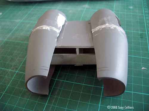
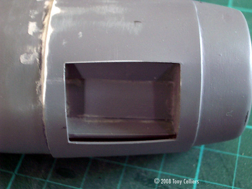
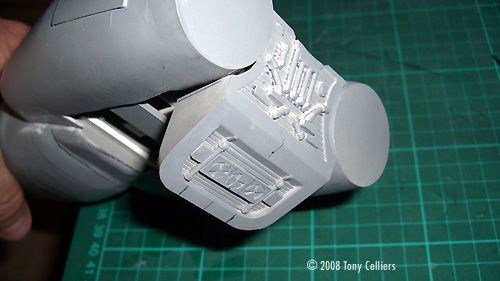
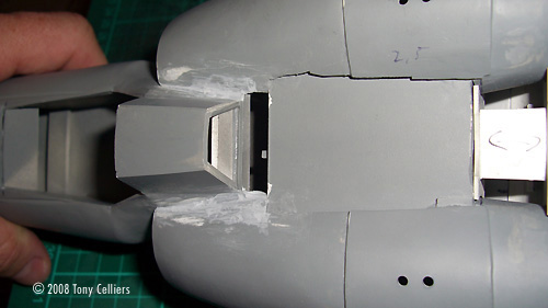
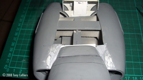
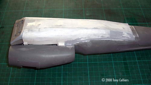
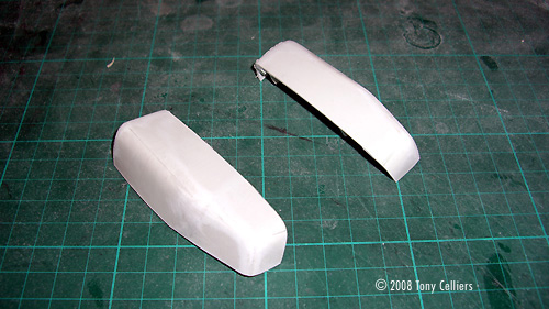
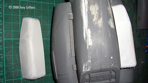
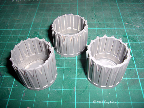
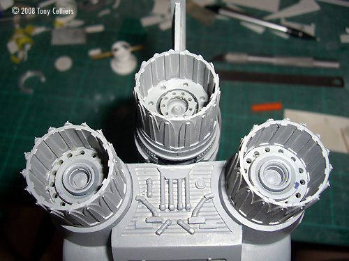
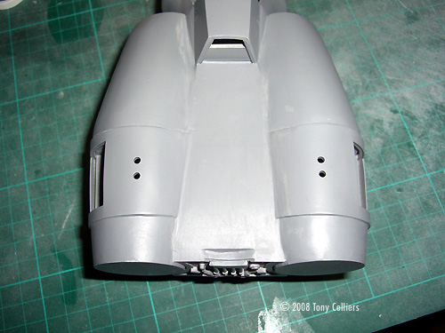
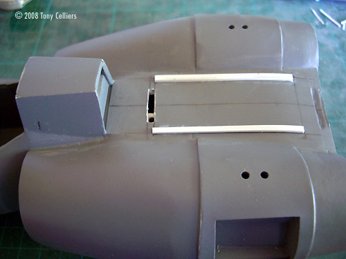
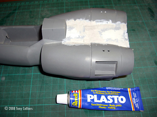
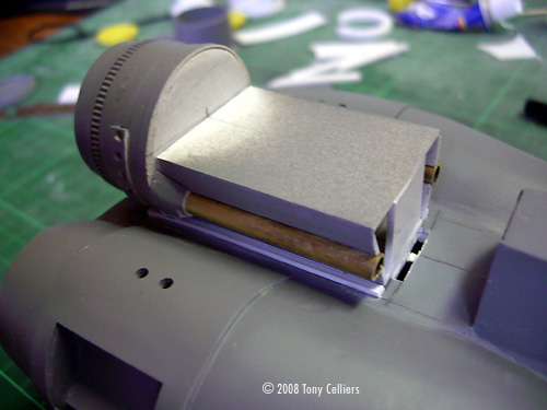
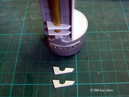
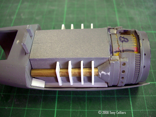
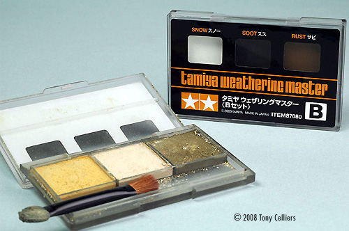
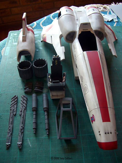
Image: Joining the vacuformed fuselage halves Image: Adding the raised nose detail Image: Main engines joined Image: Recess for exposed engine detail Image: Rear fuselage detail affixed Image: Upper fuselage closed .... Image: ... and the lower Image: Blending it together with putty Image: lots of sanding ... Image: Landing gear pods Image: Pods in place Image: Main engine components Image: Outer details in place Image: Inner detail Image: Base for the top engine & tail Image: Ready for the engine Image: Image: Components assembled Image: Side detail being affixed Image: Done Image: Recessed engine detail parts Image: Detail for the nose insets Image: Primed Image: Cockpit tub Image: Rear bulkhead Image: KEW Image: Bottom/rear thruster outlets Image: Main wing parts Image: Wing to fuselage Image: Canopy construction Image: Wire details for the engine recesses Image: Components, painted and detailed Image: All together Image: Primer applied Image: Base color coats Image: Cockpit in place Image: Tamiya Weathering Set B - good stuff |
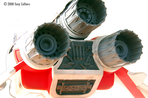
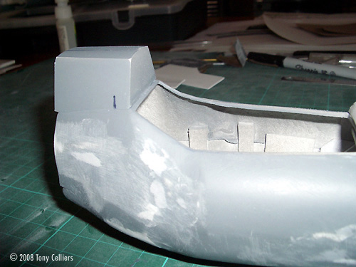
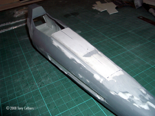
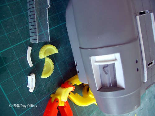
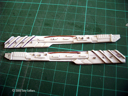
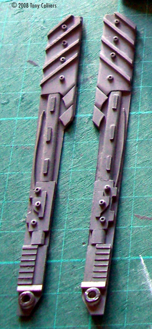
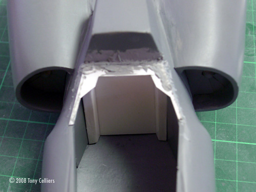
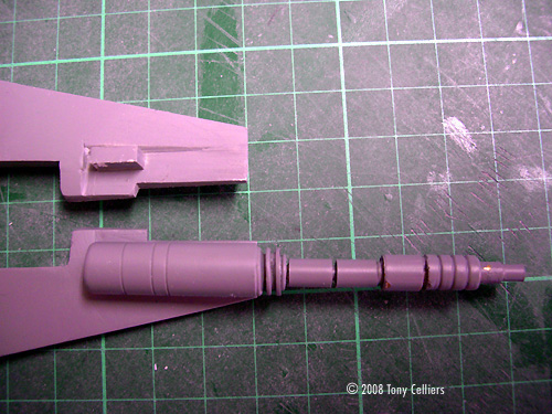
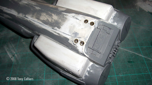
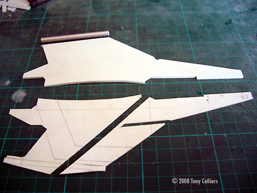
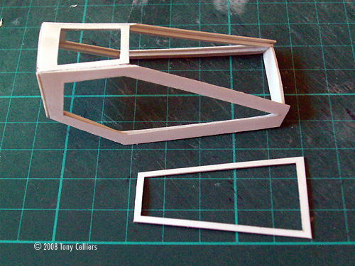
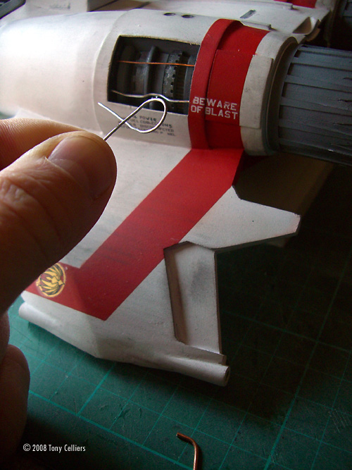
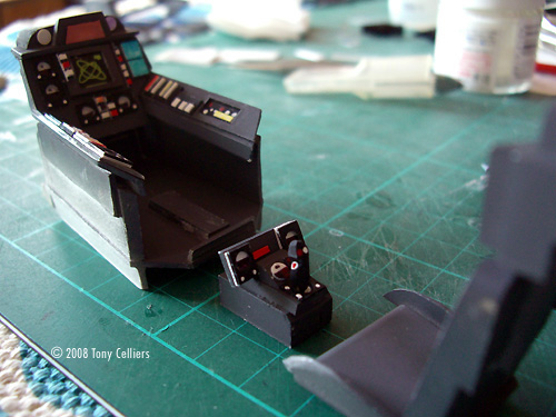
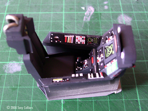
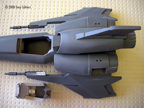
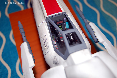
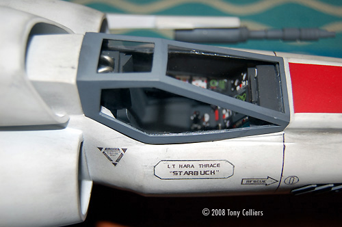
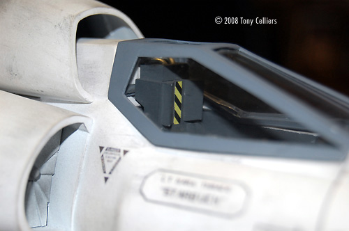
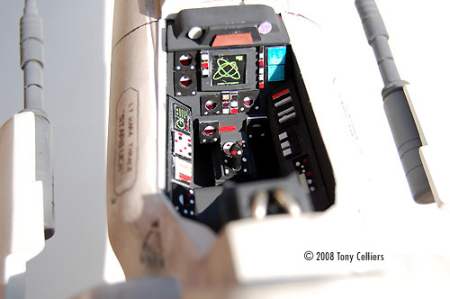
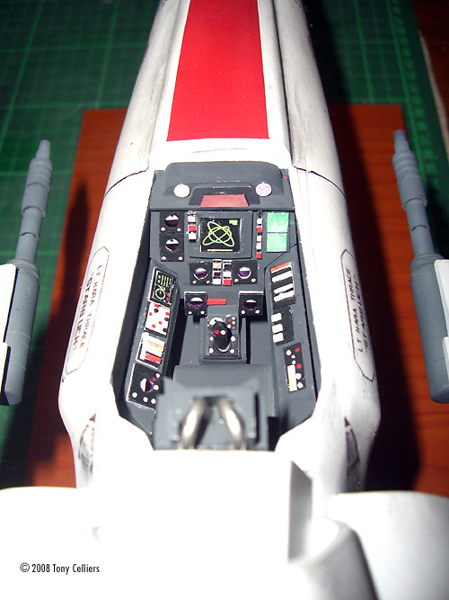
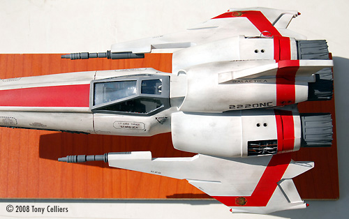
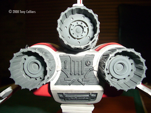
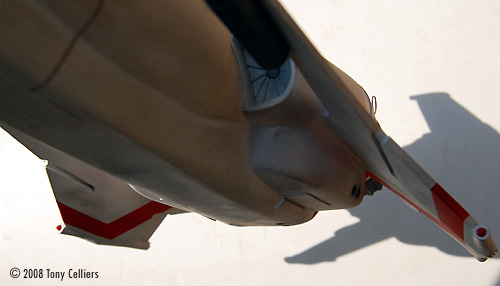
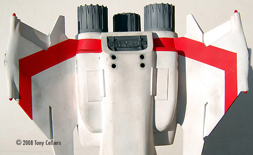
Back in the 70's I built a Viper MK1 out of balsa wood. I admired the look of the fighter and was happy to see that the shape stayed the same with the remake. It had become more slick-like, and way more interesting - called the Viper MKII. I obviously wanted one, but no kit models were available back in 2003. I therefore had no choice but to make one of my own. Three years in the making and many frustrating hours later - my model was born. Here is the construction process, in as much detail as I can remember it. I completed it during July 2008, and started at the beginning of 2005, shortly after completing the Star Wars B-Wing model (Also featured on Starship Modeler). I worked during my spare time and any other chance I could get, and also built the �Fine Molds Falcon� from Star Wars during the same 3-year period I also started with 3D modeling so time was minimal (Have a peek at my 3D models on this website). The model is 1/22 scale. This happened by chance, when I printed the excellent pictures off the Viper MKII from the �Starship Builder� site that Zoic was so kind to post. That was the size and I worked directly from them. The model is made from 3mm, 2mm and 1mm styrene plastic and various shapes scavenged from medical bottles to dental amalgam bottles. A lot of the detail was hand-cut as I couldn't find the right stuff. I used super glue for adhesive, as I found it ideal as it sets quickly and then I can carry on with the model. A normal grey primer spray can was used, and model acrylic paints for the final paint job. There were 2 phases to the building process: construction and painting Construction I decided that the easiest way to get the shape was to vacuum form it. So using the prints I made, shaped it out of styrene and foam and sanded them down to get the shape. I then used my home-made vacuum form machine to get 2 halves for the nose section and one each for the engines. I then cut and glued the 2 halves together and trimmed the engine sections. After a lot of sanding I got them smooth (they were dimpled from the foam). Once I had the shapes correct and everything glued together, I used a drill set on a mount to drill the stabilizer outlet holes on the front of the nose, and on the lower fuselage, on top of the main engine and the sides of the top engine. I inserted copper tubing into the larger holes to give them depth and sanded them down. To get the nose detail I glued a thick piece of styrene on top for the nose upper half and sanded it down (it took a lot of sanding). Then it was time for the nose and fuselage union. Using the prints I made a cage onto which to glue the 2 main engine halves and then glued the back section on to this as well. The back section detail was made from radio control tubing and hand cut plastic strips and 1mm styrene for the edges. The lines were scribed into a 1mm piece of styrene. The engine recess was cut prior to sticking a piece of 1mm styrene round the main engine section. This section was then glued onto the nose section and the area where the side intakes touch the nose section was filled using model filler. The lower fuselage detail was made in a cage fashion running a strip from the back to below. The nose section and strips were glued onto the side for the shape. Then lots more sanding was done. The landing gear pods were quite straightforward to build. Make a box, cut the corners, sand and get a headache making them look alike. Then glue them on, plenty of filler and some more sanding (man, do I love sanding). The engine outlets were made from various vitamin tablet bottles and film casings cut to the right length. My friend Gareth cut 0.5mm plastic sheeting with a vinyl cutter for the outer and inner engine detail. This was glued on as one single strip round the bottle sections as well as the inside. The interior detail was made from various round plastic bits that I fitted until I was happy with the result. The components for the top engine was made by fitting various bottles together until they looked like the reference images. The main lower section was made by a simple angled box. The top engine base was closed with a piece of 1mm styrene and filled with model filler. This was then sanded till smooth. I then added 2 strips of styrene so that the angled box could fit between. I also cut a small hole allowing the whole top component to fit snugly and not fall off when the model is turned upside down. For the top engine detail I cut a small gap down the side of the box and added a brass pipe and a half cone. I then cut small ribbing from 1.5mm styrene and glued it over the brass pipe. The tail fin was the easiest component to make. It consists of 9 pieces of varying thickness strips of styrene, glued onto a base, filled and sanded. This was then glued onto the top section and filled round the edges. The main engine side inlay detail was made from various bottles and plastic rings, cut and glued onto a base. This was then sanded to fit the recess allowing space for the wire detail to be added later. The detail on the side of the nose was actually one of the first components I built. I made it straight after I fused the 2 sections of the nose. It's once again a few scavenged pipes as well as new scratch components glued onto 1mm styrene. Details The cockpit interior was a challenge. I made it so that it could be removed, as the instrumentation detail would be added after the painting phase was completed. It consists of 3 parts and slides in with difficulty. I had to work with different designs till it looked right to me. There were just not enough images online that show the complete interior. The kit models that are now available have different designs as well. Basically I made a hybrid between different images and what little they show on BSG. All the detailing in the cockpit was made by overlaying 1mm strips of styrene with holes cut in simulating instruments and painted. It was a surprisingly quick process. The �kinetic energy weapons� were pretty easy. I used a pop rivet as a base and added varying thickness of tubes and copper pipes over the top. The main section was made from a pen casing. The pop rivet fitted over the end and was glued in place. I then cut a recess on one side of the pen casing so that it could be fitted and removed from the wing. The lower thruster vent holes were drilled with an electric drill and filled with copper piping, sanded and filled to be even with the lower hull. The canopy was made from 3mm strips of styrene and 1mm strips glued over the top. I left a gap inside for the clear plastic sheeting to fit into once the paint job was complete. Finally, I inserted different thickness copper and silver wire bent to shape once the paint job was complete. Wings For me these were the most challenging parts to make. I could have made one and cast it but all my silicon and resin were too old to use, so I had to make 2. Believe me making two look the same was no easy task. Besides, the shape the angles on top had to be precise as your eyes are drawn to the wings. I cut a base layer and 4 separate pieces, 2 for each side. I then glued each piece on and used a belt sander to sand the angle down. I did this with each side (4 angles per wing) and then used filler to refine the angles. I glued 2 pieces of piping onto the end of each wing and filled round them with a gap at the end for the antenna (pictured in final model photos). I left 2 gaps in the base layer at the edge where it joins the viper body. This was used to fit styrene strips that was inserted into the body, adjusted and glued at the right angle. I then filled and sanded the gaps. Painting The base coat was spray can grey primer. This brings out the detail and shows where filler etc is needed. When all was set and all the flaws that I could see were gone I happily whipped out my Badger 360 airbrush and painted the grey and white base coats. I used Acrylic Modeling paint for all the paint work. The white, greys and red were all flat colors. I masked off the cockpit and rear detailing before painting the flat white. I then used a pencil to mark off the red stripes and used electric insulation tape and pieces of paper to hide all the white. Unfortunately I had to do some of the white over as I had red over-spray (always make sure you cover up). Detailing Once all the paint-work was done I got onto the weathering process. I find weathering adds character to any model, as long as its not overdone. I was happy with the result. I use a camera lens cleaner for all my weathering work. I like the fact that you can move the fibers in and out for harder and softer markings. My weathering material of choice is the excellent Tamaya weathering master set from Japan. Lovely for mixing as well as sniffing in - seriously it's good stuff as long as you apply a clear coat over the top preventing smearing from grubby fingers (Hint, don't let people play with your models). |
|
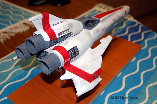
Once the weathering was done I applied the decals. 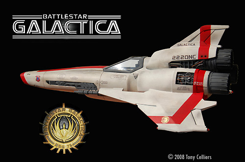 I would like thank Jimbo from JBOT decals for coming through on the decals, they really look great. All I did was give Jim the model scale and hey presto, there were decals (perfect fit) and Jim can give decals for any model and size, I highly recommend his product. |
|
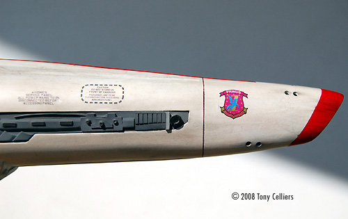
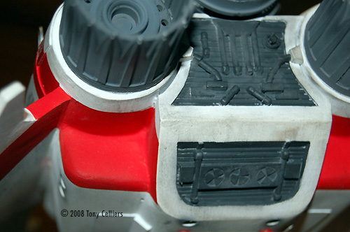
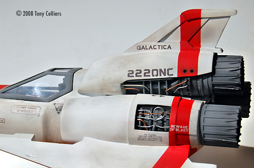
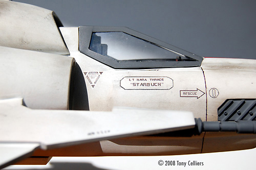
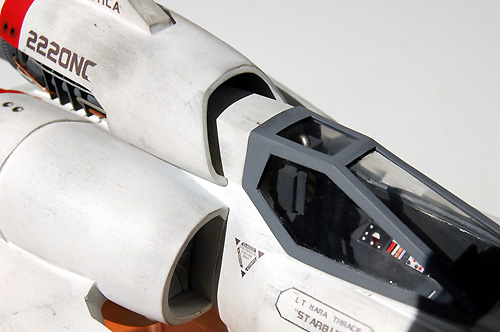
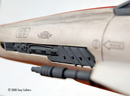
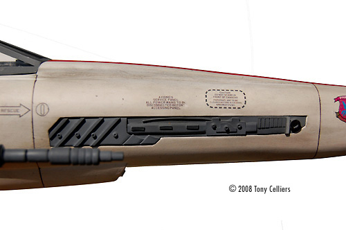
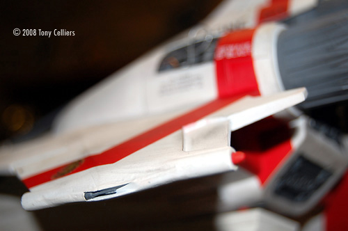
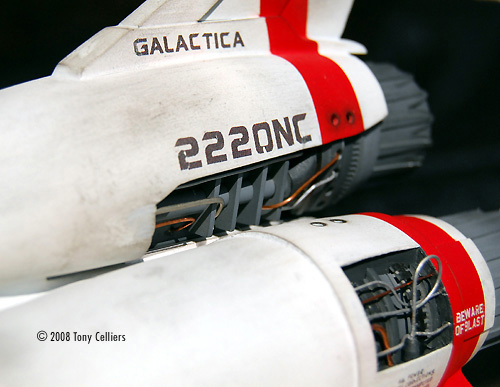
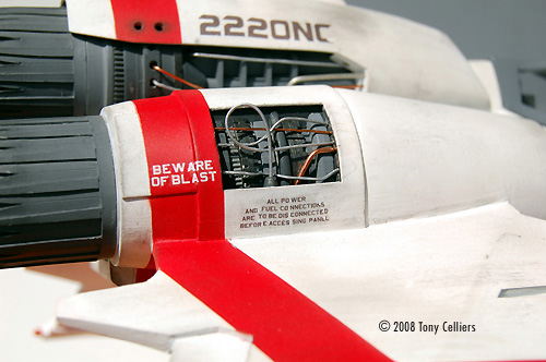
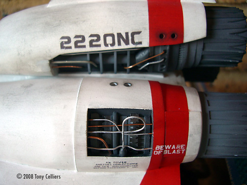
Image: Sub-assemblies complete Image: Right/rear view Image: CAnopy and cockpit, from above Image: Closer Image: Looking in Image: Cockpit detail Image: More Image: More Image: Fuselage, from above Image: Inner engine detail Image: Main gear pods Image: Rear, lower fuselage Image: Main engine intakes Image: Nose Image: Right/rear detail Image: Closer look, left side Image: Port side Image: Starboard, detail Image: Higher Image: Gun and nose detail Image: Other side Image: Wing antenna Image: Wiring Image: Other side Image: Closer look |
After the decals were applied I did a bit more weathering and applied a final coat of Clear and base to keep all the decals and weathering on the model. Conclusion And that's it. Please mail me if anybody wants specifics about the construction. I would also like to thank Nadine, my wife, for putting up with all the hours I spent in my den building this great model. |
![]()
This page copyright © 2008 Starship Modeler™. First posted on 15 October 2008.
![[Please click to enlarge]](tc_viper2/01_Mouldsforvaccumforming.jpg)
![[]](tc_viper2/09_Bottomextension.jpg)
![[]](tc_viper2/11_01_Outerstripsforengineoutlets.jpg)
![[]](tc_viper2/12_3rdenginecomponents.jpg)
![[]](tc_viper2/15_Insidetopcover.JPG)
![[]](tc_viper2/18_Taildetail.jpg)
![[]](tc_viper2/20_Mainenginedetail.jpg)
![[]](tc_viper2/23_Cockpitcomponents.jpg)
![[]](tc_viper2/29_02_Cockpit2.jpg)
![[]](tc_viper2/34_Redprimarylines.jpg)
![[]](tc_viper2/36_Completedwethering.jpg)