
|
By Tom 'Warped Speedster' Kowaliski - images & text © 2006
This was a seven year build. I worked on it on and off during several other model projects. I included a few descriptive photos of some of the parts used to make it. The recorded photos are far from complete though. The early stages of construction were not recorded at all. Many of the shots were taken just before painting. I hope they help tell a story that you can imagine for yourself. |
![[Please click to enlarge]](blackwind/00-1The BlackWind.jpg) |
|
Image: More components Image: Port nacelle parts Image: Details Image: Shroud Image: From the other side Image: Hull components Image: More details Image: Rear notch Image: Stabilizer Image: Ladder rungs Image: The hull, from the front Image: Front notch Image: Boom components Image: More Image: Details Image: Closer look Image: Pontoon tank Image: Starboard nacelle parts Image: Closer look Image: Drum mounting Image: Cockpit Image: With pilot Image: Canopy Image: Six pin hatch Image: More canopy detail Image: Bottom of hull Image: Piping detail Image: More detail Image: Tank car domes Image: Still more detail underneath Image: Belly camera Image: Camera details Image: Camera mount Image: Chin scoop Image: Anti-grav dome Image: Meanwhile, back on the bench.... Download more images of the finished model (ZIP archive) |
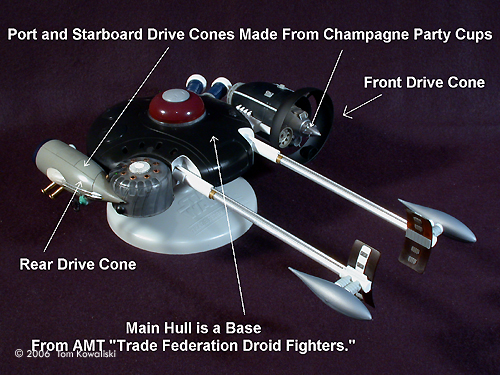
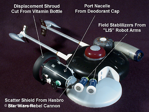
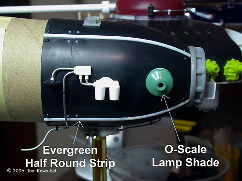
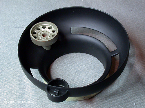
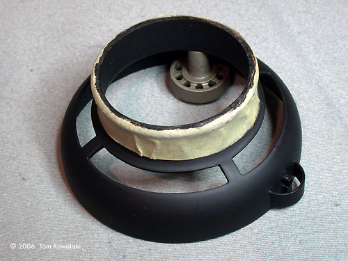
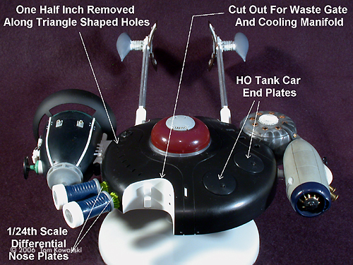
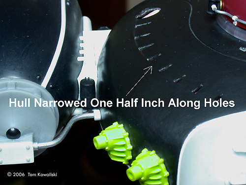
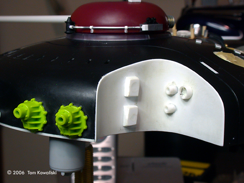
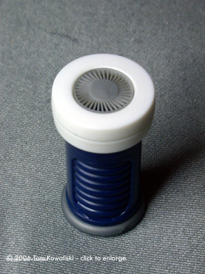
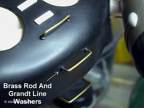
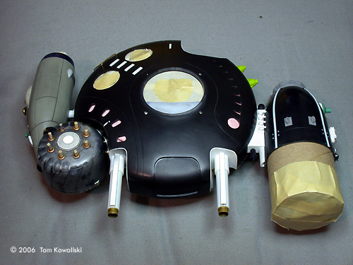
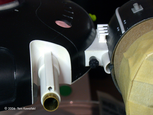
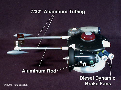
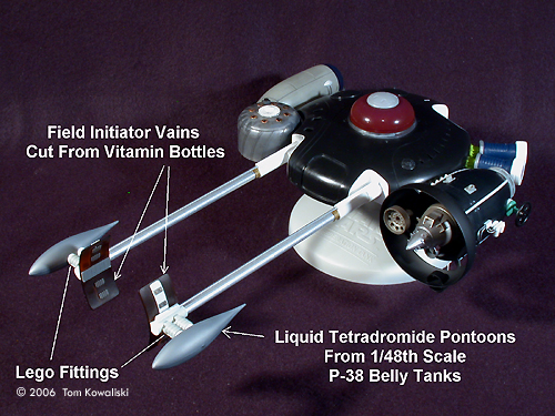
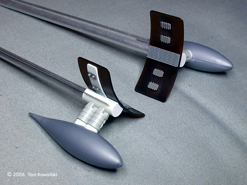
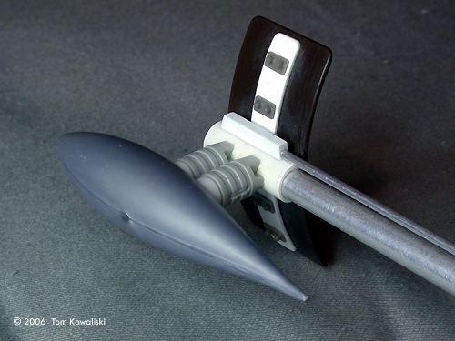
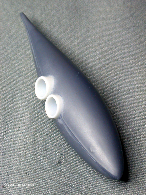
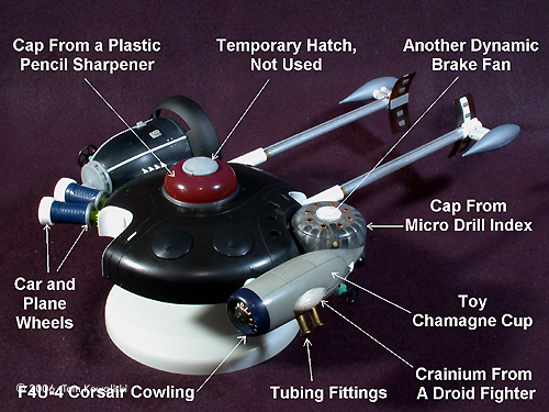
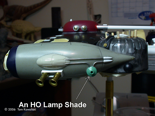
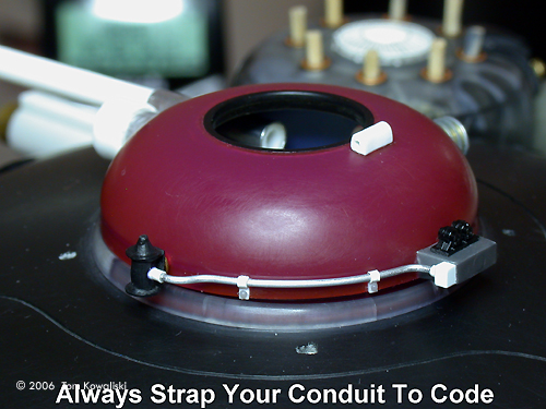
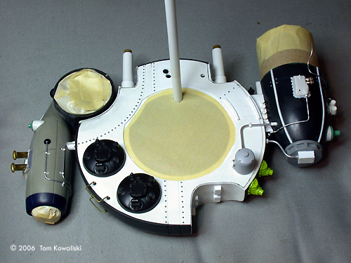
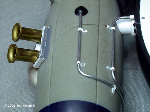
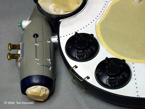
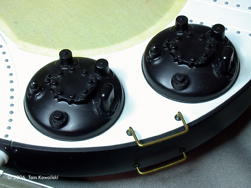
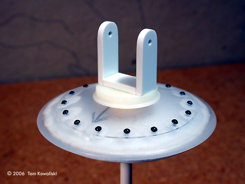
Looking at the early drawings I'd made of this ship, I'd already anticipated using the black plastic base that comes with the AMT "Trade Federation Droid Fighters" kit. It's a Star Wars model from 1998. I'm very familiar with its saucer shape and have used it for many modeling projects. And again, it was perfect for the "Chopper" I intended on making here. The model is about twelve and a half inches long by about nine inches wide. In 1/35 scale, that's 36 feet fore and aft by 26 feet at the beam. It just fits in my display case. The Port Nacelle Actually the port nacelle housing (the “Sucker Drive”) was the first phase of the ship I concentrated on seven years ago. It was built around an old Ban deodorant cap (when they used to be hard plastic). The housing is divided up into four sections via Evergreen half rod strip. The big outer fairing around the nacelle is cut from a 2 ˝” plastic vitamin bottle. Three radial slots were cut out around the fairing shroud by hand with an X-acto blade. The inner drive cone was made from a little plastic champagne party cup. I cut the stem off and sanded it to a point. A bunch of little Evergreen square plates (beckoning plates) were glued all around the nose cone. A 1/32 scale semi truck wheel was used for the draft calibration gear just to the right side of the cone. The nacelle's rear scatter shield is from a Hasbro Star Wars rebel cannon. A 1/25 scale oil pan mounted on the bottom of the housing captures any matteron residue condensing in the tetradromide soup. An O-Scale brake wheel and lamp shade was used for the side valve wheel and valve gear housing (it's a maintenance by-pass valve). I then made the decision that the Black Wind was going to have exposed rivets. So “Grandt Line” provided all those little details for the port nacelle and for the rest of the ship too. Other model railroad goodies, car parts, watch parts, and aluminum rod (for conduit) helped make it all look functional. The little aluminum rods were all very easily bent around various drill bit sizes. All the conduits around the nacelle housing were secured with “Stand Off” straps which let them run freely just above the nacelle's skin and outer ribbing. I don't have pictures of the lighting array inside the nacelle but it's lit with 8 red and 8 green flashing LEDs. They're mounted around the inner drive cone and flash forward through a .005 inch thick circle of Evergreen plastic stained with Tamiya clear (green and smoke) paints. Kinda hypnotizing. The Hull Chopping began on the port side of the hull. I narrowed it by about a half inch along the curved row of holes using a circle cutter. This would delude the perfectly round saucer look, which I didn't want. It also helped narrow what would otherwise have been a very wide looking hull and engine array. The front “L” shaped cutouts facilitated space for the forward telescoping booms. The rear cutout provided a relief for the duel matteron waste gate manifolds and the outboard cooling system. A rounded section was cut out of the hull's starboard front quarter for the drum shaped field generator to nestle in later. Before I filled in all the cutout sections I began to realize that the hull was too shallow in proportion to the big engine housings it would support. So I removed a quarter inch strip from the bottom of another saucer base I had and glued it to the hull's bottom edge. After being feathered in it immediately looked better. I then proceeded to use Evergreen .020 sheet to fill in the hull's notches and cavitations. I simply bent them into the curved cutouts and super glued them in place. The bottom edges of the bent pieces were re-enforced with some 1/4” square stock glued to their flat sides. This also helped keep their bottom edges straight and square. A rectangular hole was also cut out of the ship's nose with an X-acto saw and then a new section was recessed behind it. It was glued in with CA and then feather sanded into a tolerable appearance. The ship's forward sensors are presumably housed behind that recess. With a pencil I drew several scribing patterns directly on the ship's hull before I chose one that looked cosmetically sound and accentuated the function of the ship. I used my circle cutter again for the curved lines, and an X-act-o saw to follow the pattern around the top deck. The saw works really well on the deck's domed surface to connect one curved scribe cut to another, very controllable. The saucer section houses 17 red flashing LEDs that blast upward through the deck's eight tiny triangle shaped orifices. The two telescoping front booms (non-functioning) were built from aluminum and brass, and Evergreen tubing. The curved “field initiation vanes” were also cut from vitamin bottles and detailed with locomotive vents and naval ship goodies. A couple ribbed Lego fittings were modified to support each of the 1/48 scale P-38 belly tanks. The Lego fittings represent light duty repulsor lifts for the front boom section. The tear drop pontoon tanks presumably store the tetradromide gas (the secret sauce) in a liquid state. Two 1/48 scale Cessna engines halves were glued back to back and used for the rear outboard cooling manifold which mount in the deck's rear cutout. Some Lionel O-Scale plumbing pipe and fittings were cut up and reconfigured to enter and exit the manifold there. The dual waste gates are mounted in that same rear cutout. They were built from two “Sprint Car” air filters with Evergreen tubing for the exhaust pipes. Now that the hull had the booms temporarily inserted, there was a straight point of reference to measure by. So the port nacelle could now be mounted to the hull and sorta lined up with them. I made a little transition box with Evergreen plastic to adapt the deodorant cap's compound curvature to the saucer's radius. The transition box was glued to the hull first. Then I spent a whole day lining up the nacelle housing with the box and the booms. I fed the engine's wiring through three small holes into the hull first, held my breath and then glued it all in place. My first lucky break, everything glued on straight after all. Evergreen .040 sheet was then used for the hull's belly skin. Laid against the hull's bottom edges I just traced the outline shape and cut it out. It glued in place without too much turmoil and then was finish sanded to the hull's outer edges. With the circle cutter again, I made a 3” circular opening in the belly plate to allow access to the wiring and for the remaining appendages to be glued in place later. That opening would also later receive the 3” belly dome that housed the female stereo jack used to mount the ship on its display stand. An X-acto blade was used in typical fashion for scribing any straight lines on the belly plate. The Starboard Drive I now went to work on the starboard ”Pusher Drive.” I'd decided to match its shape with the portside drive cone. So I dug out another plastic party cup and carved it into another drive cone. Then I added an F4U-4 Corsair engine cowling, contoured into its tail section. The spoke shaped contraption inside the cowling is a section of a plastic wedding bell ornament with an HO clean-out hatch mounted in the center of it. |
|
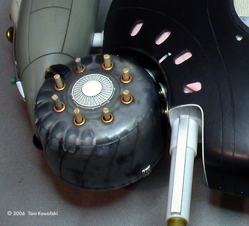
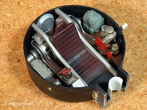
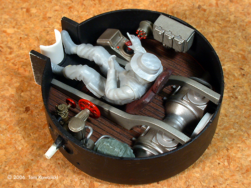
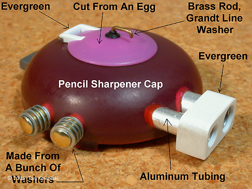
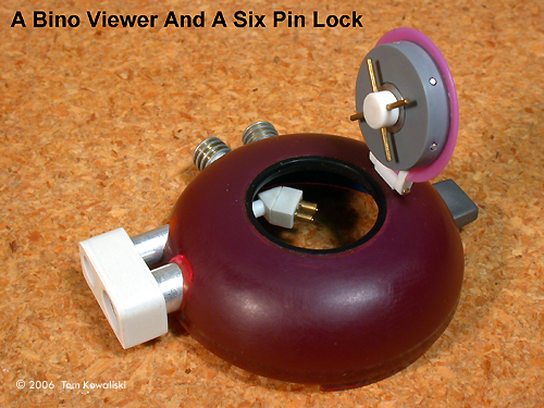
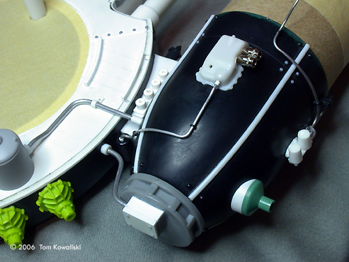
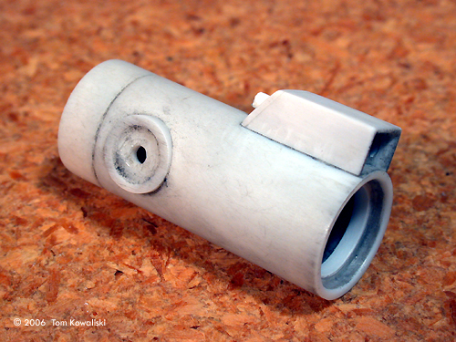
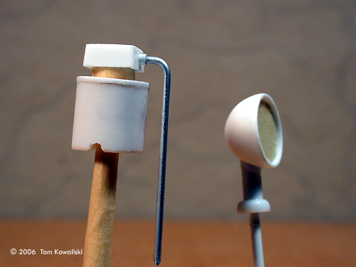
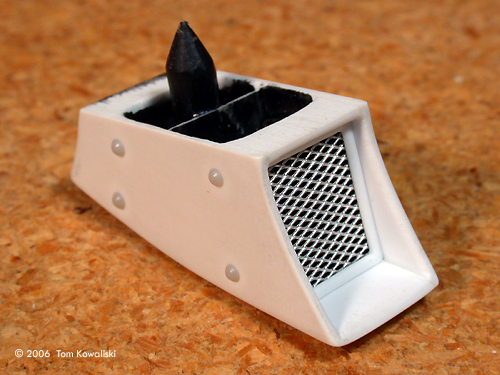
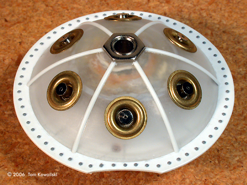
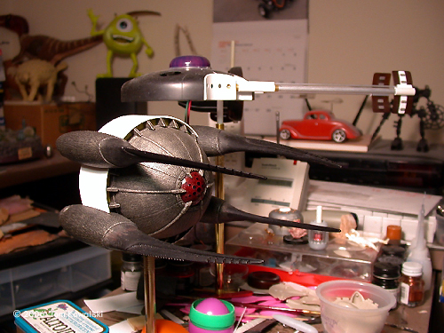
For the starboard drum I sacrificed a clear domed cap from a pin vise drill index. It was shortened about 3/8ths of an inch. A locomotive dynamic break fan was used on top of the drum as a vent. The drive cone's nose would wrap around the side of the drum and attach with a 6-32 screw and CA. But first some scribing had to be done for the cone's panel sections. Again, an X-act-o saw was used free hand for that job. Then I also scribed some curved lines all around the drum using the circle scriber again. I just held the drum down in a jig built on to the work bench that would let it rotate. Then I locked the scriber's point into a specially made hole at a distance of about five inches away. There the blade would repeat the desired (vertical) cut radius sixteen times as I turned the drum. Just for fun, I cut the cranium off of a Droid Fighter (easily recognizable) to use as a blister on the side of the drive cone. The dual waste gate exhausts below the blister are tubing sleeves for Ľ inch plastic water lines. The valve housing on the side of the cone is an HO lamp shade. Another O-Scale break wheel worked nicely for the valve wheel. More aluminum rod for the piping finished off the port drive's yin and yang appearance. Sixteen LEDs of various colors flash through the eight little grommet openings in the top of the drum, and five green LEDs fire through the nacelle's rear end. The Cockpit At this point I had no idea how I was going to mount the starboard drive nacelle to the hull so I turned my attention to the ship's cockpit. It's built inside a round tub made from a section of yet another vitamin bottle. The seat, cameras and viewers, metal framework and instrument panel are all built from Evergreen sheet and strip. The gauges were cut from round stock. Pre-scribed Evergreen sheet was used for the seat. It was easily curved into a reclining position and then a straight back was glued behind it to lock it into position between the frame members. It was textured with thick flat black enamel paint and then dry brushed a dark leather color. The simulated wood floor was made from pre-scribed sheet too. Holding an X-act-o saw blade sideways, I raked it along the pre-scribed lines to get the wood grain effect. It was also painted flat black and then dry brushed with a rust color. The floor consol to the right of the seat is from a car model. The little T-handle joy stick is scratch build. The ventilation unit behind the seat is two halves from a funnycar differential housing mounted end to end and glued on to the deck. The round vent behind them is another locomotive brake fan. The valve gear to the left of the seat is made from HO break wheels and locomotive details. Finishing the Starboard Nacelle After some deliberation I finally decided how to mount the starboard drum/cone assembly to the hull. With only a very tight clearance to work in, I dreaded the next little bit of assembly work I had to do. I decided that four 1/8th inch brass tubes in the drum would somehow pass through four receptor fittings in the hull's right side cutout and then all be super glued in place. That's a very simplistic description of that part of the project but that's essentially it. And that part of the hull cutout now had to be beefed up internally with metal reinforcement and a lot of CA if it was going to support the somewhat heavy drive nacelle. Again, I spent another entire day lining up the obtuse shapes of the drive cone to the ship's saucer section with almost nothing to measure by for reference, except an eyeball. I lucked out again as it seemed to finally glue straight and true. Next, the wiring from the drum slipped through the four 1/8 inch tubes and into the main hull. All the wiring was now pulled into the hull so I could now solder in all the resistors and make up all the joints. After all the connections were made I was left with just three wires waiting to be connected to the stereo mounting jack. The jack would have to wait until later though so I folded the wires into the hull cavity. Stabilizers Two field stabilizers now needed to be built to mount to the left side of the hull, directly behind the port nacelle. The arms that came with the “Lost in Space” robot kit looked good for that apparatus. The seam lines were on the flat sides of the arms and were easily sanded away. Some model car wheels were glued back to back for the stabilizer head. I sunk another HO scale dynamic brake fan into the wheel's open ends. Aircraft wheels from a 1/72 scale Nieuport bi-plane were used at the other ends for looks. Next, two 1/24 scale car differential nose housings were then attached to the hull's radius. After drilling out the bi-plane wheel holes a bit, the stabilizers mounted nicely to those differential plates. Finishing the Cockpit I now turned my attention back to the cockpit again, mainly the dome. It was made from a plastic pencil sharpener. The hinged hatch cover was built from a section cutout of an Easter egg, and scrap plastic for the hinge. I gave the hatch a “Safe” like appearance with a six pin wheel lock under the lid. The dome's twin camera barrels are aluminum tubing, with Evergreen for the rectangular lens box (shield). The cockpit's inside “Bino” viewer was made from a couple 1/8”x1/4” pieces of Evergreen cut at a 45 degree angle to aim towards the pilot. The eyepiece barrels are just tiny pieces of brass tubing. The viewer mounts to the end of the smaller right hand camera. It gives the pilot a direct visual through that lens. The ship's other two cameras (top and bottom) are viewed on a monitor screen inside the cabin. The cockpit is internally lit with three white LED flood lights. Bottom Details All that was left to complete was mostly the belly detail. It's funny, the bottom ended up with more stuff than the top side. The vast majority of the ship's rivet work ended up on its belly. That took considerable time, but still somehow it was a very gratifying task that I really didn't mind doing. I then found some great looking Lionel tank car domes that had some nice clean detail. They were bigger than I'd anticipated using but they mounted cleanly to the bottom rear section. More automotive details were used (top and bottom) around the hull's starboard radial cutout where the field generator drum mounted. The belly camera/floodlight unit was all scratch built with Evergreen tubing and strip, and then mounted to the starboard drum's bottom cover plate. The camera pivots all around and is used mainly for planetary surface observation. The drum's bottom plate is cut from a 4” round plastic sphere from Michael's. It received some Grandt Line rivets and a circle scribed around its center section. I then made the main belly dome from a three inch plastic sphere, again from Michael's. Evergreen half round strips divide it up into six sections. They met at the bottom center where the Ľ” female stereo jack had been threaded and super glued in place. Its hexagonal locking nut worked great as the place to butt up the dome's six dividing strips. The dome's flat plate section also received Grandt Line rivets all around it to match the rivets on the rest of the ship. The dome also has six anti-gravs incased in it. I used six big metal grommets with necklace clasps inserted inside them to represent the ship's main repulsor lifts. More belly piping was done with various aluminum rods and fittings. I tried to have a pipe connector where ever a conduit connected to an apparatus or to a junction box on the ship. They also had to have tiny conduit straps for effect. They were made using the thin plastic skin from small Plastruct (coated) metal rods, and very thin Evergreen strip for where the screw would attach through the strap. The last few details I decided to incorporate into the bottom side were a couple scoops and a diesel air horn. The midship scoop next to the rear TDR tank (an N-Scale milk container) was from a Snap Draggin's model kit. It was de-chromed and given an inner aluminum mesh screen and framework. The larger front chin scoop was made from Evergreen stock. It's partially patterned after the smaller scoop but has an exit vent. It also received an inner frame and mesh screen for consistency. A few Grandt Line rivets finished it off. The air horn is from a G-Scale locomotive. I just liked the idea of blowing a horn whenever the ship entered a viable atmosphere just to make some noise and to scare away any indigenous wildlife. Balancing Act The very last thing that was left to do before painting was balancing the ship. The long forward booms obviously made the ship quite nose heavy. The only thing for it was to fill the very tail end with as much lead weight as I could. Well, I can tell you that every nook and cranny was stuffed with lead. I used the lead weights that are typically used to add mass to model railroad rolling stock to help them roll smoothly. They have an adhesive side that makes them rather easy to install and glue in place. The ship sits fairly buoyant now when perched on a stand. Not perfect, but it's more balanced than I ever though it would be. Paint, Decals and Weathering I had photography in mind when choosing a color for the ship. Though it's called Black Wind, that color wouldn't have been good for photos so a dark gray was chosen over black. And I felt that a real dark gray color just looks like scruffy black anyway. But the finished model photos are sort of deceiving; the ship is much darker than they make it out to be. Anyways, “Testors Schwarzgrau” gray was airbrushed on for the darker tones. It was lightened a bit for the lighter gray sections. Just enough contrast to give some definition along the scribed hull patterns, and dark enough for a ship bearing the name “Black Wind.” After painting, I micro sanded the entire ship with 800 grit wet/dry paper to remove any specs of dust and lint. It also takes the tooth out of the painted surface and just gives more of a realistic finish. Most of the metallic pieces on the ship (inside and out) were sprayed with “Testors Jet Exhaust.” I just like the magnesium look it gives. But the port drive cone was done in regular chrome silver. I used Microscale railroad decals, with some success and some frustration. A lot of “Maintenance of Way” and locomotive data sheets were used, mainly ones that best described the function of the particular part of the ship they were placed on. Many had to be pieced together of course. I used Games Workshop paint for the washes and weathering. I'm very used to working with it. It creates very convincing moisture stains but can be nicely feathered too. I always have a cup of clear water ready to control the intensity and consistency of the effect. For the top deck I used black washes only. I don't like too many grunge colors busying up the look of a vehicle's natural shape or base color. It's personal to each individual, but I wanted the weathering to enhance this model firstly, and dirty it up secondly. But for the hull's bottom side I do like getting a little dirtier so I also used some dark brown washes there. I also weathered the port drive cone too as best I could, but I find silver to be the hardest paint to weatherize. After a coat of clear dullcote the ship was almost done except for a little more 800 grit micro sanding to get it all smooth again. After sanding I took a paper towel and lightly buffed it to give just a tinge of sheen to the flat finish, which I think also adds to the realism of the sanded surface. It's almost a semi-gloss look but it looks better than semi-gloss paint, I think. The Last Detail For reasons I can't remember, the belly dome couldn't be glued to the hull's bottom until all the painting and weathering was done. So the three wire leads that had been tucked away in the hull now needed to be pulled out to be soldered to the female jack in the belly dome. The wire didn't allow too much clearance to work in. And there were just so many other things in the way that I was extremely glad and lucky to get that annoying bit of assembly work done without a gluing mishap. After installing the dome, there were still a few conduits that now needed to attach between it and the hull. With the last conduit finally pushed into place the model was actually done. I'll never forget the day it was finished. It was a surreal moment that almost seemed wrong after seven years. The spot where it had sat for so long staring at me was now an empty lifeless void. A very strange and personal modeling experience. |
![]()
This page copyright © 2006 Starship Modeler™. First posted on 4 January 2006.
![[Please click to enlarge]](blackwind/01RawMaterials.jpg)
![[Please click to enlarge]](blackwind/08RearHullLaterProgress.jpg)
![[Please click to enlarge]](blackwind/39RearViewofFinishedModel.jpg)
![[Please click to enlarge]](blackwind/40RightSide.jpg)
![[Please click to enlarge]](blackwind/41Onbase.jpg)
![[Please click to enlarge]](blackwind/42LeftFront.jpg)