
|
By Andy "Bad Andy" Wacht - images & text © 2003
This is an IMAI 1/48 variable LEGIOSS. Thus far, this has been my favorite mecha design - ever since I was a child. After having built two in my younger years and learning of their demise during my college years - I decided to procure a few during the rebirth of my interest in modeling. I have since been successful and decided to build one up ... Construction This mecha has seen much scrutiny (as many transforming mecha do) in the execution of its models. Mainly in the proportions, there is a lot of 'anime magic' going on during the transformation process. According to the original line art, what looks accurate in 'armo-soldier' will suffer in 'armo-fighter' mode, and vice versa. I love the sculpt Imai did for this in 'armo-soldier' mode but do whole-heartedly agree that it looks funny in 'armo-fighter' mode. |
![[Click to enlarge]](aw_legioss5.jpg) |
|
|
Therefore, it was of no concern of mine to actually transform this model (risking paint scrapes and scratches anyhow) so I did not bother with any of the cockpit or pilot parts. I also glued the landing gear doors (on legs) shut, since they were prone to 'flopping' open. This kit was designed and sold in the 80's. The fit & finish of the parts leave a lot to be desired when compared to current kits being designed today. Most noticeably:
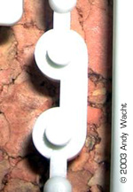
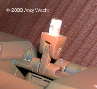
As a whole, just getting the kit to look good building it box stock is difficult enough...but that didn't stop me...I wanted to do some things different. Modifications This kit does not compare to contemporary kits as far as poseability is concerned. I wanted this to change. I referenced a page that described some excellent modifications to increase the mobility and poseability of this model. Trouble is I don't understand Japanese, so I had only the images to go by... These modifications were:Now, the tricky part (since I had actually assembled the head before I decided to do this mod- which would not have been nearly as tricky if the head was unassembled at this stage.) was getting a spare polycap to fit this rod and to place it into the head. Luckily, I had one that was not too far off, and all I had to do was sand the rod slightly to reduce the diameter of it. I was able to place the poly cap into the head, but still had to figure out a way to keep it there. I cut two thin slivers of 2mm sheet styrene (maybe 2mm wide or so) and glued them each to the bottom of the head, one on each side, flush with the surface, yet in a way to create a 'track' for the polycap 'arms' to allow the polycap to slide fore and aft (this preserves the original placement of the head for transformation...even though it was not a concern of mine, I still wanted transformation to be possible) I once again took some .5mm sheet styrene and glued this to the bottom of the now 'upper' section of the torso, the chest, we'll say. I used another section of styrene rod and located a polycap that would mate to it. I drilled a hole just large enough for the rod in a piece of 2mm sheet styrene and glued this to the .5mm piece already attached to the bottom of the chest section. I then glued a short section of rod into the hole I had drilled for it. |
|
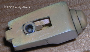
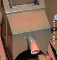
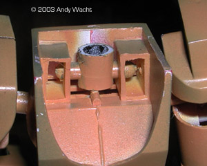
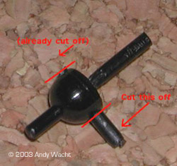
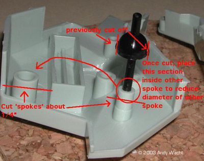
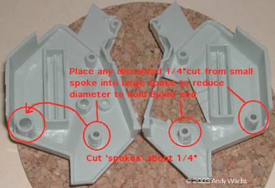
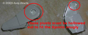
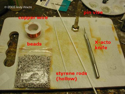
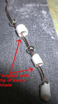
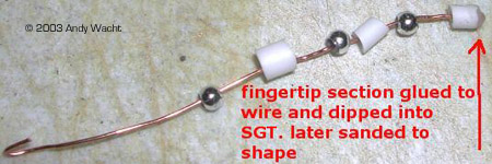
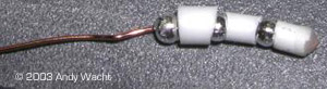
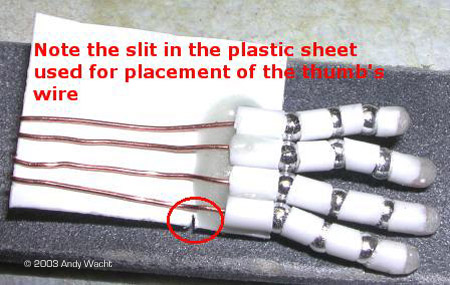
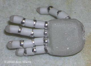
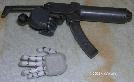
I took the polycap it would mate with and used two pieces of hollow rectangular styrene to mount it in the groin area, one styrene piece on each inside wall. This was done by drilling a hole just large enough for the polycap 'arms' in the broader sides of each rectangular styrene piece, previous to gluing them to the groin walls. Once the glue had dried, the chest piece had an extending rod of styrene that mated nicely to the polycap and provided twisting motion for my legioss. Luckily, each end of the ball joints fit perfectly inside the mounting 'spokes' inside the large lower leg halves. I trimmed the 'spokes' in the lower leg halves to allow for the movement of the heel and toe pieces. The tricky part was hollowing out the pivot points in the toe and heel sections. I used a dremel to grind away just enough material inside the pivot points of the toe and heel sections to allow for a snug fit for the ball section of the Kotobukiya joints. With the ball joints in place inside the pivot points of the toe and heel sections, I then was able to place the ends of the ball joints into the now trimmed 'spokes' in the lower leg halves and glue the legs together. Whew! While these modifications are great I also wanted a few more things accomplished: Each rod piece was placed into the pin-vise (with no bit) so I could 'hollow' or 'bevel' the inside edge with my Xacto blade. I wanted to create a conical, beveled edge for each 'knuckle-bead' to recess into. One end of the copper wire was bent and one piece of rod was glued to this bend. This would form a fingertip. The fingertip was 'dipped' in SGT and then sanded to fingertip shape. Here is a pic of my mostly completed 'thumb.' Note that I used a lightly larger diameter rod to imitate that larger muscle the thumb is attached to. I then cut four more pieces of styrene rod and glued (SGT'd) them to a piece of styrene sheet. The copper wires were fed through these and wrapped around the other side of the styrene sheet to provide a little tension. Note that in the pic you see the 4 fingers, there is also a notch I created to guide the copper wire for the thumb into position. I then placed the thumb's wire into the notch and wrapped it around the styrene sheet also. SGT was applied to the wires to glue them into place. I applied more SGT to build up the hand and prepare it for sanding and shaping. Here is a picture of my near completed hand and a fully-painted and completed hand. I drilled a hole in the wrist for my Bjoint wrist upgrade. That was it for the mods...now onto finishing! Painting I decided against the typical paint scheme seen in the series and opted for a custom 'desert' scheme. I used a custom color mix of Liquitex acrylics: red, yellow, black and white to come up with the main body color I like to call 'Doggy-doo brown.' The arm/leg joints and feet sections were painted with black and grey colors. I applied a variation of 'max' shading technique using simple black as my darker shade. The clear parts were painted a Navy blue and the eyes were a custom mix of fluorescent green, dark green and silver. Finishing After painting, a few light coats of Future floor polish were applied to seal the base coat. As for decals, I did not want to use the markings in the original scheme. I opted for a few different decals I had laying around from other kits...including a few from a cool set of 'nose-art' decals I purchased from the Starship Modeler Store. A healthy dose of Microscale's Microset and Microsol solutions were applied to 'snug' them down into details and panel lines and help the edges blend to the paint coat better. I then applied an oil wash to bring out the panel lines and other details. I like working with oils as they and their solvent (odorless mineral spirits) do not react with the acrylic nature of the paints and Future coat. Everything was then sealed with Future and then clear coated with Testors' dullcote. I experimented with some drybrushing (my first time) of silver along certain edges and the gun especially, to give a worn and faded appearance. I'm fairly happy with the way it came out (although it is hard to see easily in the pics) Base The base was a wood plaque purchased from a crafts store. It was then stained and many coats of Future were applied. I bought a thin brass rod for the support of the model and drilled a hole in the base for the rod. I wanted to be able to 'pose' the model on the rod so I decided to mount the model on a ball joint. The ball was drilled and glued to the end of the rod. I drilled a hole large enough to accept the ball in the lower torso (the groin, ouch!) of the legioss and used spare styrene sheet to mount the female end of the joint inside the lower torso. This allows me to angle the mech while on the rod. The edges of the base were masked. On the helpful recommendations of fellow SM discussion board members, I located some sandstone at a local pet store in the aquarium suppliessection. I proceeded to smash this chunk with a hammer in order to break it down into smaller pieces and create some 'scale sand.' I sprayed some adhesive on the base and poured my sand onto it. I then glued a couple pieces of my sandstone onto the base, using a mix of white glue and CA (which gave the glue a thick substance, allowing it to conform to irregularities in the rocks, quick drying attributes and dried clear as well.) To simulate grass, I bought some large inexpensive paintbrushes with long bristles and cut a few chunks off. I staggered the ends of the bristles and trimmed the bottoms even, then glued them to the scene. I think the overall appearance looks pretty decent, yet perhaps a tad out of scale? but that's OK. Overall As far as trying to rate this kit, it is inline with many offerings during the 80's, but can not compare to the quality, fit, and finish of styrene models of today. The Hasegawas and Bandais have certainly raised the bar for mass-produced styrene kits over the years and it seems this is one kit that has suffered in comparison. This was a learning experience for me, being my first experiment attempting modifications and scratch building parts. My execution has still left flaws that I may later practice a few 'battle-damage' techniques upon. Yet, what the original kit lacks in fit, finish and quality will make for quite a good challenge. Such a challenge however, that it may be time for a brief respite before I undertake another one. |
![]()
This page copyright © 2002 Starship Modeler™. Last updated on 21 January 2003.
![[Click to enlarge]](aw_legioss1.jpg)
![[Click to enlarge]](aw_legioss4.jpg)
![[Click to enlarge]](aw_legioss6.jpg)
![[Click to enlarge]](aw_legioss10.jpg)