 |
|
|
|
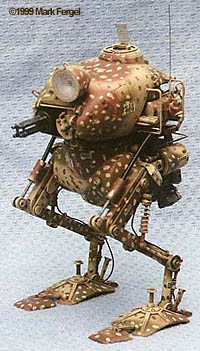
By Mark Fergel
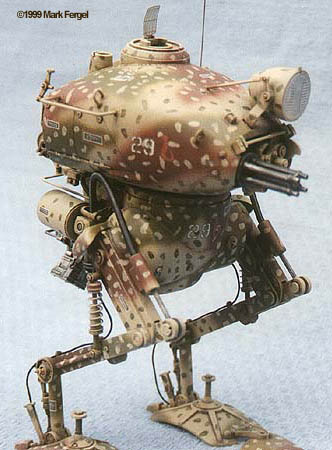
If you haven't heard of the Nitto S.F.3.D. (now "MzK ZbV 3000") series, get out of bed, put on some clothes and run, don't walk to your nearest hobby store or online vendor and order at least one now. These are some of the most complete multi-media kits available in the sci-fi genre. |
|
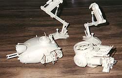
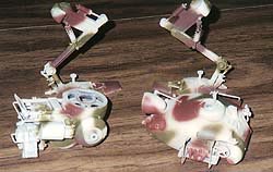
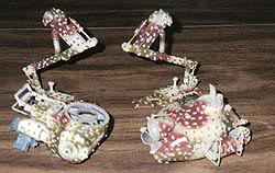
First Impressions Overall quality of the molds is quite good and molded on detail is exceptional from two-cylinder motorcycle like engine to the weld beads. Of exceptional note is the separately molded bolt heads. Just make sure not to remove these from the sprue tree of carpet. The type of plastic used seems like a cross between that used by Hasegawa and Tamiya. Slightly brittle and hard yet softens well when using liquid cement such as Tenax or Testors'. The kit also contains a small packet of multi-media consisting of rubber hoses, springs, brass rod and one piece of photo-etch. When was the last time you saw these in an American Sci-fi kit release? Parts Breakdown While mold quality is quite good, part fit is slightly average. In fact, several parts hardly fit as well. Assembly starts with the quad machine gun. These components fit together well but several of the pieces are marred by ejector pin marks. Luckily, these barely show up after assembly. The placement of parts in step 2 is a little unclear. Part b9 also leaves a large gap on its backside. Again, this is barely noticeable after assembly. Step 3 covers the assembly of the searchlight. The Japanese release of this kit contains an actual led for use within the light. This is not included but noted in the instructions. Step 4 deals with the assembly of the main body and continues into step 5. Part fit is good for the most part but sanding and a small amount of putty is needed. Being an armour type subject, you could also make some weld marks at the joining of these seams by using stretched sprue and then applying liquid cement to the sprue and attacking it with the edge of a hobby knife. The combined assembly of parts a1-a4 also results in a large gap towards the front that will require some sheet styrene and a contour gauge for a tight fit. The addition of a small electric motor for the machine gun would also take place at this time. However, the motor is not included therefore parts b39 and b40 are not needed. The various detail parts for the main body are attached in step 6. Part b32 does not fit properly and requires trimming for a smooth fit. This is difficult since it is a very delicate piece. Part b21 slide into a small hole on the main body. However, that hole is extremely oversized and leaves a very large gap that will require a small amount of putty. Assembly that begins in step 6 continues in step 7. Part b26 contains two very large ejector pin marks. There is no way of getting at these to sand or fill properly. Also, while the instructions do not indicate this, part b26 must be attached prior to part b34. The location of part b37 is somewhat vague, as there are no alignment marks. Part b38 is "supposed" to attach to the main body but is entirely the wrong contour. I tried to sand it to fit but eventually gave up and left it off. Part b46 is a hatch of some sort and has the option of being displayed open or closed. Of note is parts b22-b24. While not mentioned in the instructions, brass rod is included which may instead be used to replace their fragile plastic counterparts. Step 8 describes assembly of the engine. The joining of parts c8 and c9 results in some very large seams. Some of these may be sanded with a needle file but most are unreachable. There are no significant problems encountered in step 9. Step 10 concerns the lower torso. A small amount of sanding is needed to clean up the joining of parts c1 and c2. Part c32 in step 11 contains some very nasty ejector pin marks, which must be sanded off. Take care when removing parts c16 from the sprue. I lost one of them to the plastic eating carpet monster. Step 12 joins the various sub-assemblies to the lower torso. Part c7 has some significant fit problems and will require some trimming in order to fit properly. Step 13 concerns assembly of the included figure. I have yet to fully assemble him but there were gaps in the joining of the front and back halves that will need to be filled. Detail is quite good though. Assembly of the legs begins with steps 14 and 15. Rubber sleeves are utilized to maintain friction on all the moveable parts. Part fit on all components was quite good and only minor clean up was needed. There is an option during assembly at this point. You have the choice of using the single-piece coil-over shock absorber or building the 5-piece version, which includes an actual spring. I chose to go with the later, as it is much more realistic. Final assembly happens in step 16. This is where the four sub-assemblies (body, torso, and right and left legs) come together as one. For ease of painting, I waited to complete this step until after painting. Painting There are three different painting/decal options. I chose to go with one of my own. After all, how many times have we sci-fi modelers heard, "It doesn't matter how you paint it. It doesn't exist anyway." I went with a pattern used by German Tank forces in WWII. First off, I primed the entire kit in black, making sure to get into those hard to reach areas. A splotchy coat of Polly Scale acrylic tan (custom mix) followed this. The next color was a dark green followed by a rust-brown. The splotches were then painted by hand. I also hand painted the engine in neutral gray. I wish I had left it off during proper assembly but I had not planned to paint it a separate color. After the paint had dried sufficiently, I applied a coat of Future floor polish to prepare the surface for decals and an oil wash. The decals are very thin. In fact, to thin. They end up being slightly transparent when applied. Also, the decals do not release from the backing very well when using water. A setting solution is needed in order to properly remove the decals. A solvent is also recommended in getting the decals to sit snuggly on the model. |
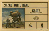
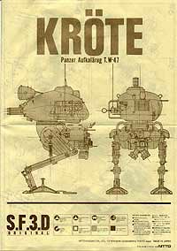
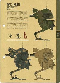
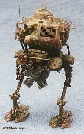
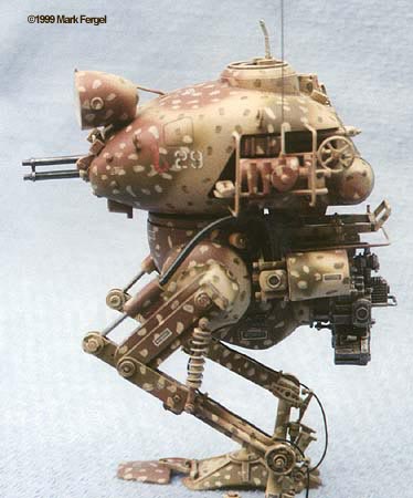
Click on any of the three images
|
|
After letting the decals dry for a day, I applied a wash of burnt umber oil paint to all of the nooks and crannies (No, it's not a Thomas' English Muffin). When applying a wash, I first brush the area with clean mineral spirits followed by my wash. This helps force the oil paint into the corners and keep surrounding areas clean. Be careful when handling the objects as you apply the wash as oils dry very slowly. After allowing the wash a few days to dry, I over-coated the entire kit with a clear flat. In my never ending quest for dead flats, I have tried nearly every flat coat out there and have to say that Model Masters new line of Acrylics is one of the best I have come across yet. This is dead flat folks. The next stage involves dry-brushing the edges of the kit. Normally, this isn't a real big deal but when working with a camouflage pattern such as this, it is a little trickier. I added white to my originally colors and dry-brushed the edges for each area separately. This was followed by some light pastels around some of the cracks and crevices as well as around the legs. I then lightly applied a coat of Polly Scale dust to blend and protect everything. Final Thoughts This kit is a real hit or miss. There are some definite problems in the production of the kit but the end results definitely pay off. Given the age of the kit, I will let the some of the machining flaws get by; however, the "Jerry" kit was much better in terms of fit and quality. I don't recommend this kit to someone just starting out but for the intermediate to advanced builder, this is a fantastic kit and is a real change of pace to what most of us are probably used to building. As Woody (Toy Story) once said; "If you don't have one, get one!" |
![]()
This page copyright © 1997-99 Starship Modeler™.
Last updated on 13 May 1999.