
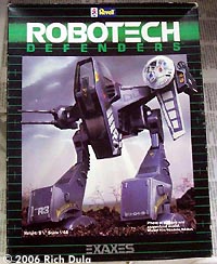
By Rich Dula - images & text © 2006
After I got home from WonderFest 2006, I wanted to sit down and work on a relatively easy kit that I could just have some fun with. |
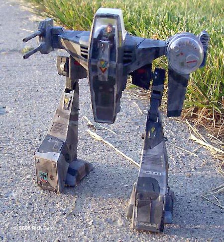
![[Please click to enlarge]](rd_exaxes_SunRtSideFull.jpg) |
|
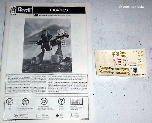
Image: Instructions and decals
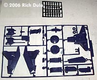
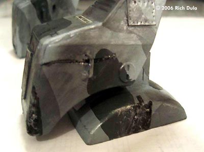
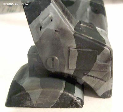
Image: More parts Image: Very basic cockpit Image: I'd hate to be the guy on the bottom.... Image: Engine area Image: Detail is OK Image: Left foot Image: Right foot Image: Another front view Image: Right/front Image: Left side, close Image: Rear view Image: Closer look |
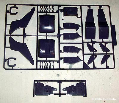
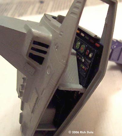
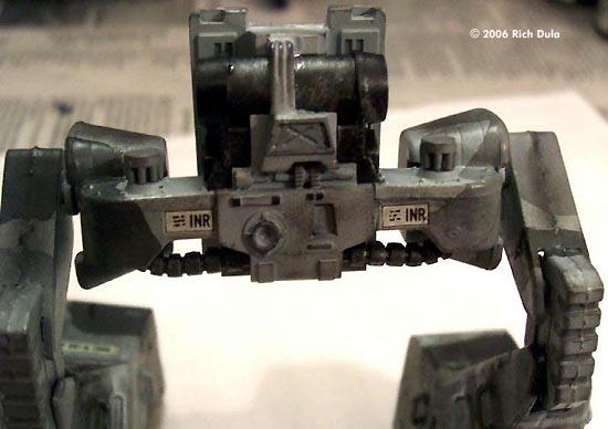
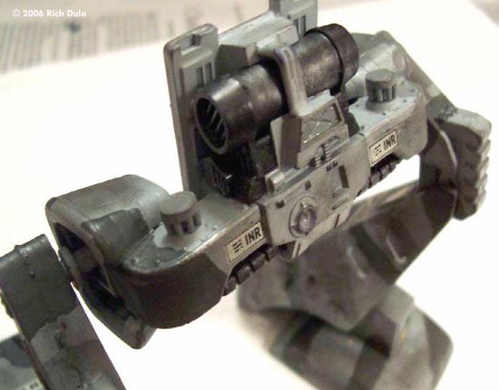
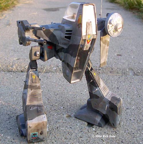
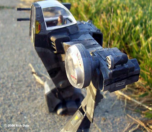
I had purchased a Robotech Defenders Exaxes kit on eBay in 2005, and the kit had been sitting on my stock shelf for some time, so I figured “what the heck” and decided to build it. Now, I should clarify that I have built this kit before, back in the 1980's when it was first released by Revell. That kit was a casualty of a BB gun war sometime around 1985, taking heavy impact damage before a lit M-80 was dropped right between its legs. What You Get As John Lester noted in his preview article about this kit, the Exaxes was originally the Ishform from Studio Nue's Super Dimension Century Orguss anime series. In fact, the Revell kit still carries the Orguss ID tags on the sprues, as well as the A, B, and C designations. The kit includes three primary sprues of parts that are molded in purple, one secondary purple sprue (with the instrument panels), one sprue of clear parts, and a sprue of 28 rubber polycaps.The Exaxes was designed as a two-man recon 'Mech for use in rough terrain. It is lightly armed, with a twin-barrel cannon mount on the right shoulder, and a large sensor dish on the left shoulder. Aside from the cannon, the 'Mech doesn't appear to carry any other weapons. The instructions that are provided are laid out in a 12-page booklet with 39 steps. The last step shows the placement of the decals. The decals themselves are fairly representative of those on most kits during the 1980's. They have lots of carrier film and are generally thick. A couple of the smaller ones were slightly off-register, but still didn't look too bad. The Build-Up For an older vintage kit, this one is not that bad. There was minimal flash on the parts, and some minor sinkholes. There were four main sinkholes that I encountered during construction, two that were on the exterior of the kit, and two on the interior. The first step in the instructions deals with building what is more or less the waist of the 'Mech. I immediately started painting the base color on the various parts prior to assembly. The actual engine section was painted with Testor's flat black paint and then dry-brushed with MM Chrome Silver. You have to do your detail painting before assembling the two engine parts because they slide into a circular section on the back side of the waist area. Once they are in place, you will have one heck of a time trying to paint them. Steps 4 and 5 are the first point where you encounter sinkholes. The exterior ones that I mentioned earlier were on parts B15 and B16, which are the lower brackets coming from the engine area and bending into the hip portion of the 'Mech. I assembled the parts as shown and attached them to the engine area. Then I simply filled in the sinkholes with some super glue and sanded the glue down flush with the surrounding surface. In Step 7 it isn't clear from the instructions whether parts B5 and B6 are supposed to be glued in place, or if they are supposed to be left loose. These parts act as the hip joint covers and cover the pivot points for the legs. I ended up attaching them with super glue and locking them in place, otherwise they were flopping all over the place and could (and did) slip off quite easily. Step 10 starts construction of the legs, and here is where you might need a Dremel or a small cordless drill. Steps 10 and 11 deal with building the knees of the 'Mech, and you will need some clamps to hold these parts together while they're drying. Likewise, you will also need the clamps during steps 13 and 15, when you are attaching the upper legs by positioning the parts with pins running through the parts assembled in steps 10 and 11. |
|
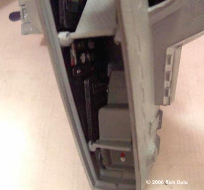
This is where your tools will come in handy. On a couple of the parts, the polycaps were not large enough to allow the pins to pass through during assembly, even though I was using the largest diameter polycaps provided with the kit. I ended up using a 9/64 drill bit to open the polycaps up a little bit after they were already installed in the knee halves. When you assemble the feet (steps 16 to 19), I highly recommend painting them before you start assembling the leg halves in step 20. The feet are attached to the legs via a two-point pivot near the toe, but it is difficult to reach some of the areas after assembly. While you are assembling the legs, it is best to glue the leg side plates into position, then let them dry before putting the cover plate on. Also, be careful in steps 21 and 23, as you have 12 small handles (part number A13) that are very easy to lose. I ended up losing one, but covered the holes with a patch made to look like replacement armor over an impact site. Step 25 shows installing the two crew members in their seats before installing the seats in the body sections. I left my crew members out until I had decided whether to use the seated figures provided or to use some other standing figures that I had in my parts bin. Step 26 begins assembly of the cockpit, and this was where I encountered the two interior sinkholes that I mentioned earlier. They were on parts 24 and 25, which are the cockpit panels. Fortunately they are located at the bottom of the panels, which are flat, so you won't have to worry about removing any detail areas. As before, I simply filled in the sinkholes with some super glue and then sanded the areas. I did have to use my clamps to hold the panels into the body sections while they were drying to prevent the panels from bowing inward toward the seats. This is where I deviated from the instructions a little bit. The cockpit area is set up as a dual cockpit, with the pilot's chair up in the head of the 'Mech, and the crew in the lower torso. There is a large open space under the lower crew seat, and I didn't like that. I looked through my parts bin and came up with the forward landing bay from an old Ertl Imperial Star Destroyer (about ľ inch square). With all of the wiring molded on the part, it looked perfect for an interior panel. I painted it, gave it a little dry brushing, and installed it in the cockpit. I decided to skip 27 (cockpit window installation) until the end, and went directly to step 28, which involves attaching the back of the 'Mech. The problem is that you have to paint the inside of part C1 or you will see purple inside your 'Mech when looking in through the cockpit windows. I clamped the body sections together and let them dry for about a day. I also attached the cannon mounts at this point (step 37 - parts C19, C12 and C13), and the sensor pod (step 32 and 33 - parts C11, C10, C5 and C6) so I could see if there were any gaps and to make painting of the shoulder areas easier. I did find one large hole in the upper rear section of the left shoulder, which I patched with some sheet styrene. It almost looked like a mounting point hole that had been incorrectly cast, but according to the instructions there wasn't anything to be attached at that point. The only other change that I made was a substitution in step 36. I didn't like the part supplied by Revell for the antenna (part C14), so I clipped the antenna off at the base, installed the base in its location, and after it dried, used a pin vise to carefully drill open the center section. I then used super glue to attach a short length of guitar string for the antenna. I won't have to worry about antenna breakage later. The only real problem in terms of fit is with the bottom window at the front of the cockpit. Depending on how tightly you clamped the body halves together during assembly, you might have to sand the sides of the window down in order to get it to fit. I used a No. 11 blade to shave some of the window down, and then evened it up with a sanding stick. After repeated dry-fitting, the window finally fit. The top window fit without any alternation. The last major assembly was painting the crew figures and putting them in. I decided to use the supplied figures and add additional ones outside the 'Mech later. I painted the uniforms MM Rust, detailed with MM Interior Green and Testor's flat black. The flesh tones were painted with Acryl II Skin Tone Base and carefully dry-brushed with Skin Tone Warm Tint. Detailing I decided from the beginning that the last thing I wanted to build and display was a BarneyMech, so I started looking into alternative paint schemes. I settled on using a triple-gray paint scheme for an urban recon 'Mech, with MM Lt. Ghost Gray as the base color, and varying sections of MM Dk. Gull Gray and MM European 1 Gray. The cockpit was painted MM Lt. Ghost Gray, and the panels were painted flat black. I used various paints to simulate the instruments, and then dry-brushed the panels with Chrome Silver. I wanted this to look like a 'Mech that had been in the field for a while, so it's pretty dinged up. After I assembled the major sub-parts, I attacked them with my Dremel to show damage. Nothing major, but some dents, scratches, impact craters, that kind of thing. I painted those sections flat black to make them stand out a little bit. I also attached patch panels made of sheet styrene to various points around the 'Mech. After I glued them in place and let them dry, I chucked a dressmaker pin into my pin vise and used it to simulate rivets in the panels. I went around the outer edges of the panels, and sometimes through the center on larger panels. For the decals, I used a paint brush to apply Future only to those areas where a decal would be placed. I applied the decal, and then sealed it with more Future. I touched up any areas that needed it, and then dry-brushed with MM Chrome Silver over the whole 'Mech, picking out details as I went. I then used a Q-Tip to apply pastels for weathering and damage. Once everything was done, I sealed the whole kit with Testor's DullCote. After the DullCote dried, I installed the clear parts using Elmer's glue. Conclusion This was a fun kit to build, and it's still fairly common. Assembly was easy, with quick common fixes for any problems encountered. Any modeler with moderate experience in building styrene kits should have no problem with this kit. There are many modifications that could be made if desired. For example, I considered removing the left-shoulder sensor array and installing a scratchbuilt missile launcher. I decided at the last moment to build this as a recon 'Mech rather than as a light attack 'Mech. Everything else I have in my stock is an attack 'Mech, and I wanted something different. If you like 'Mech kits, and you enjoy having something a little unusual sitting on your display shelf, you should definitely pick up one of these kits. |
![]()
This page copyright © 2006 Starship Modeler™. First posted on 15 November 2006.
![[Please click to enlarge]](rd_exaxes_SunFront01.jpg)