
|
The projects in this section are presented as step-by-step journals. Our intent is to delve deeper into the nuts and bolts of constructing and finishing a particular project while giving a sense of how long it takes. The subjects will range from simple kits to complex dioramas and everything in between. Authors will range in skill level, and include hobbyists and professionals. If you have a project you would like to share here, please drop us a line to discuss it. |
|
| SFSM Oberth-class Starship |
|
![[Please click to enlarge]](olb/ss_oberth/0anotherviewday.jpg)
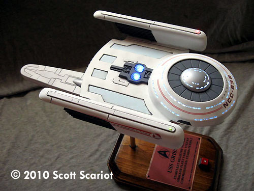
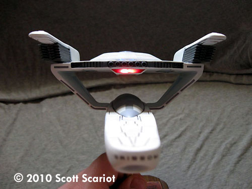
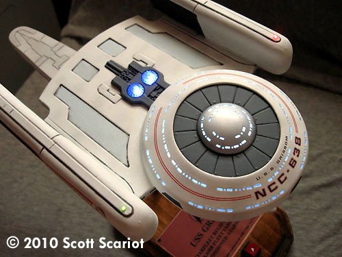
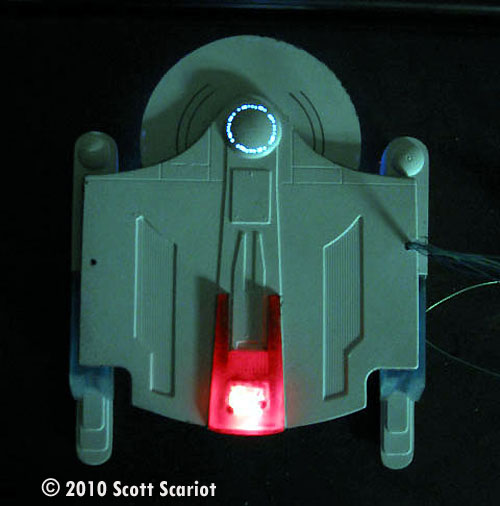
Image: Completed model, lights on |
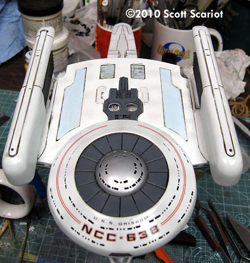
Project type: Vacuformed model with LED lighting by Scott Scariot - images & text © 2010 I originally built a version of SFSM’s Oberth class years ago after I first discovered the online Sci-Fi modeling community. My skills at the time were lousy! Since SFSM stopped making kits they have become hard to find. I was able to get one a pretty good price via the internet. It’s surprising but people are still making aftermarket resin parts for this kit. My goal is to not only build a good model but to light it up. I plan on using several techniques to accomplish this. |
|
Day 11 | Day 12 | Day 13 | Day 14 | Day 15 | Day 16 | Day 17 | Day 18 | Day 19 | Day 20 Day 21 | Day 22 | Day 23 | Day 24 | Day 25 | Day 26 | Day 27 | Day 28 | Day 29 | Day 30 Day 31 | Day 32 | Day 33 | Day 34 | Day 35 |
|
|
|
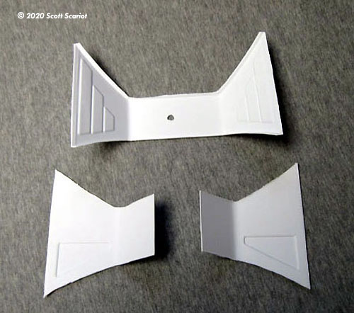
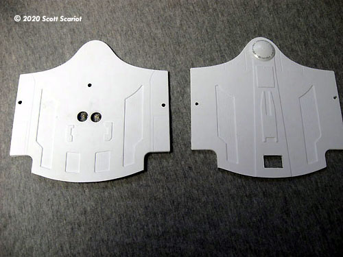
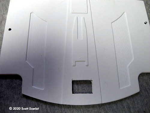
Day 1 As always, the parts were washed and allowed to dry. The kit consists of two sheets of vacuformed parts plus a small sheet of styrene. To get this kit ready for assembly all of the excess styrene has to be removed. The first time I built this kit I cut the excess off too close to the parts. This led to uneven parts. So this time I left a lip of styrene around each of the parts. I plan on using a rotary tool to remove it later. Total work time: about 2 hours |
|
Day 2 Today I broke out the rotary tool. I used a sanding drum to remove the excess styrene from each part. I left a tiny little bit of the lip to make sure I didn’t mangle the parts. I will hand sand this lip off of each part. Total work time: About an hour |
|
|
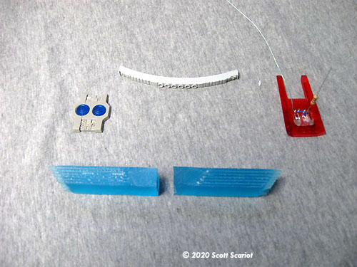
Image: Resin add-on parts |
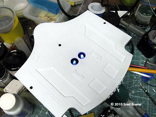
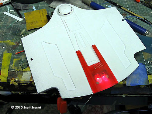
Day 3 Today I really got down to business. Now that the parts were cut out and were mostly free of excess styrene I got to work on modifying parts for lighting. JTGraphics makes a resin add on part for the Impulse engine in clear red resin. To modify this part I used my rotary tool to remove some resin in the center of the part. Once the excess resin was gone I sanded two red LEDs flat so that they would sit inside the impulse engine. I glued the LEDS into place and then wired them up. After a quick check to make sure they lit up I moved on to the main hull. I cut a small opening in the bottom of the hull so that the wiring from the impulse engine could fit inside the model. I also removed the rear bulkhead from the top and bottom of the main hull to accept a resin detail piece from JT Graphics. Now I moved on to the Impulse driver crystals on top of the ship. I bought mine from DLM, but JT Graphics sells one too. I needed two holes for the crystals. Since this part of the model is kind of thin I used 3mm Blue LEDS in stead of 5mm. I wired up the LEDS and did another quick check to make sure they were working. The biggest pain in prepping a model for lighting for me is windows. Fortunately, the model is small and so are the windows. The kit does not have any windows molded in; luckily JT Graphics included windows on their decal sheet for this model. I used a pencil to mark the area where the upper windows needed to go. I placed the decals like normal. I did coat the decals with a really light quick coat of future. Once the future dried I put a small drill bit in my rotary tool and began drilling out windows. Personally I like to do this when the battery for my rotary tool is low on power. It makes it a little bit easier to control what the drill is doing. For the round windows I just needed to drill one hole. For the larger square holes I drilled two holes side by side. Once all of the windows were drilled I used a small rectangular file to even out the larger windows. Once all the windows were cut out I sprayed the insides of the parts black to act as a light block. Total work time: 5 hours |
|
|
|
|
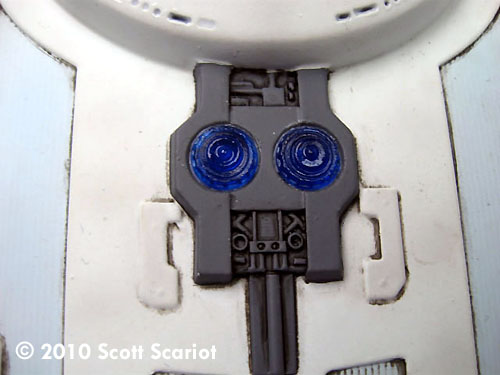
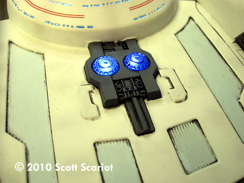
Image: Drive crystals work |
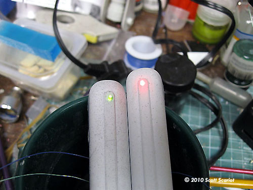
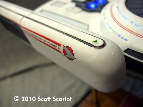
Day 4 Today was all about wiring lights. I used white spray paint as another light block and to add reflectivity to the inside of the lighted parts. I didn’t spray the inside of the warp nacelles white because the nacelles will only have one LED in each for navigation lights. I glued the resin impulse engine onto the bottom of the main hull. I also taped the two blue driver crystal LEDs into the top of the main hull. I also glued the rear resin bulkhead into place in the rear of the main hull. For the navigation lights in the nacelles I took two 3mm LEDs - one red, one green - and chucked them into my drill to file the tops down to a more narrow shape. I attached a resistor to both LEDS and then glued them into place. Total work time: 2 hours |
|
|
|
|
|
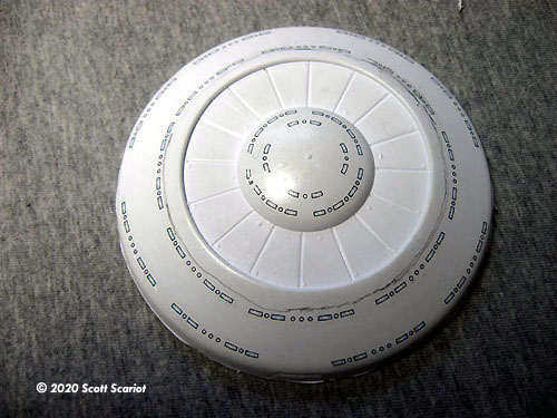
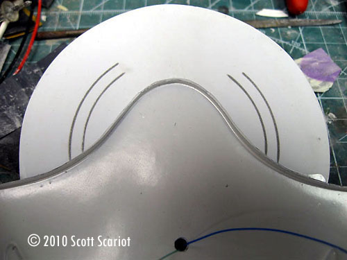
Day 5 Quick installment today. I cut the three shuttlebays out of the saucer section. Then I measured out and cut pieces of corrugated styrene to use as shuttlebay doors. Once the doors were cut out they were glued into place. Total work time: 15 minutes |
|
|
|
|
|
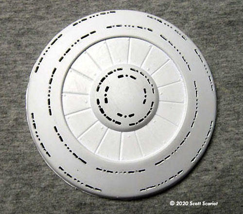
Day 6 Another quick installment tonight. Because of the way vacuformed kits are made the connection points between pieces is very thin. So to give the glue something to grab on to and add structural strength I glued three styrene tabs inside the top of the saucer section. The nice thing about vacuformed kits is that there are lots of leftover bits of styrene to use for this purpose. I also added a small length of styrene tube under the bridge just to help support the saucer. After clamping the tabs into place I attached the 3 LEDS to light the saucer to the bottom of the saucer. Total work time: 20 minutes |
| |
|
|
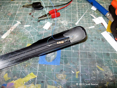
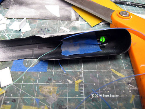
Image: Covering the LED |
Day 7 Today I continued work on the saucer and warp nacelles. I unclamped the tabs to help mount the bottom of the saucer. I bent the tabs so that they would sit on the bottom of the saucer. I glued the two halves of the saucer together. I set the saucer aside to let the glue set up. I picked up the warp nacelles. Both of these parts are very thin. This is because they are at the top of the mold and more plastic was pulled from this area. I mixed up some Aves Fixit putty. Fixit works just like regular Aves but it is opaque. It is great to use on lighted model projects because it helps to stop light leaks. I lightly scored the inside of the nacelles to give the putty something to bite into. I gently pushed the putty into the front of the nacelle and over the LED and wires. This will help stop light leaks, and will help hold everything in place. Once I had both warp nacelles reinforced with the putty I found I had some left over so I filled the rear portion of the nacelle with it. I mixed up some regular Aves putty and filled the rest of the nacelle and the entire second nacelle. I’m hoping the Aves will strengthen this part, but not add a lot of weight. I also added some Aves to the Domes on the bottom of each warp nacelle. I left the Aves to cure. Total work time: 1 hour 30 minutes |
| |
|
|
Image: Other side |
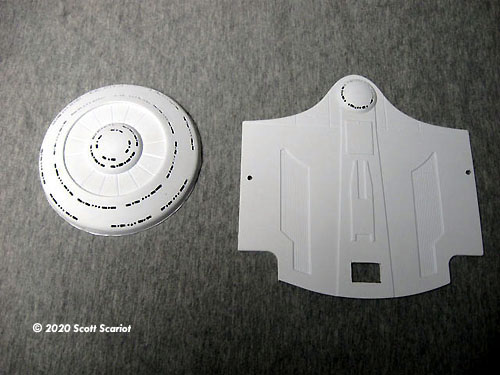
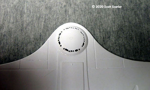
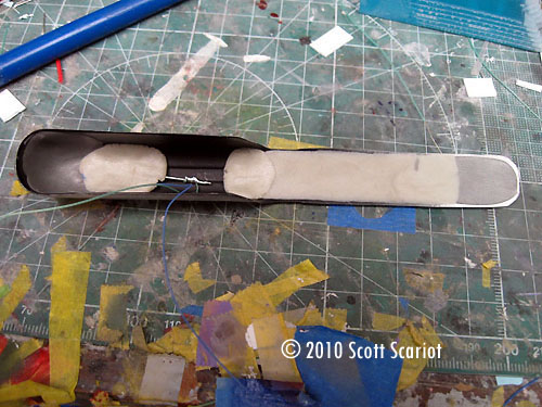
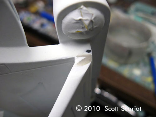
Day 8 I picked up today with the saucer section. The Aves Fixit had cured so now I had to sand the seam along the bottom. The seam was not easy to sand; even with the tabs glued inside the two parts kept splitting. To fix this I would add a drop or two of CA and then sand immediately. This would join the parts and help to fill the seam. Once the seam was filled to my satisfaction I glued the saucer onto the top part of the main hull. I used some blue painter's tape to hold the saucer in place. I used some Fixit to fill the inside bottom of the warp nacelle. I filled both of these parts, smoothed out the joints and set the parts aside to let the putty cure. Next, I added Aves to both sides of the pylon. I then placed the two top parts on and placed a weight on the parts so that the putty would set in the correct position. Now I turned my attention to the bottom of the secondary hull. There will be no lights inside of this section, but it will have to support the weight of the rest of the model. First I used a rotary tool with small drill bit to drill holes all along the oval at the back of the part. Then I used a knife to remove the plastic. Then I glued the cone structure into the part. With this part in place, I began to reinforce the inside of the secondary hull. |
|
I mixed up a big batch of Aves and smoothed it in the channel at the bottom of the part. Then I filled the seam around opening at the back of the part. I added some to the front so I would have something to glue the top piece to. I added some more to the rear as a counter weight and to help with attaching the top part. I had some Aves left so I made 8 little shelves from it and attached them to the sides of the secondary hull these would also give me something to glue the top of the secondary hull to. I also had just enough putty left that I made two rolls of it and placed them inside the warp nacelles horizontally to help add a little more strength to the thin plastic of the nacelles. I set all the parts aside to let all of the putty cure. Total work time: 3 hours |
|
|
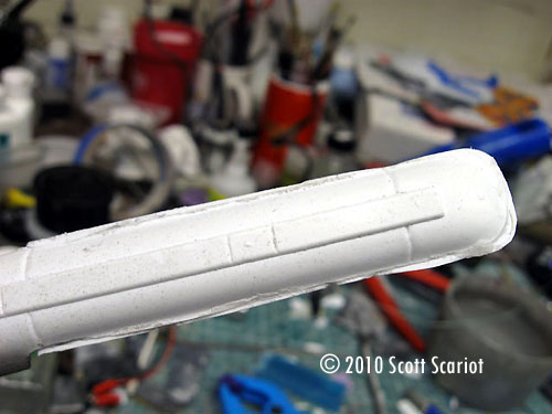
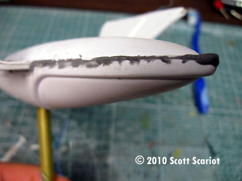
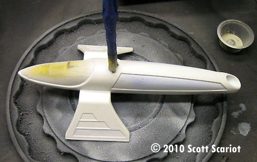
Image: Bottom of the pylons ready |
Day 9 Today I began final assembly of the warp nacelles. The putty had cured and had strengthened the plastic parts. I sanded the putty inside the rear of the nacelle smooth, and then I sanded the bottom rear piece smooth. I cut some cross hatching into the putty on both parts of the nacelle and then glued them together with CA. I clamped both parts and set them aside. While the glue dried I picked up the saucer section I began re-sanding the seam. I did have one area that split again that required more CA and sanding. Once I had the whole seam sanded I applied a narrow line of CA around the seam and I sanded it one more time, just for good measure. I picked up the top part of the main hull and glued the saucer onto the top of the main hull. I also glued the impulse crystal base onto the hull. I left the crystals off for right now. Once the glue on the nacelle part had dried I placed a drum on my rotary tool and began to sand away the excess plastic from the nacelles. I was careful no to get too close to the nacelle and remove too much plastic. After I had ground down both nacelles I wet sanded the nacelles till the top and bottoms were flush. |
|
My next step was to attach the warp field grilles. The kit explains how these can be made with sheet styrene, however I bought a pair from Angry Wives Studio. (I’m not sure if they still sell them, but JT Graphics does.) These aftermarket field grilles are a Godsend! All one has to do is glue them in place. My set was cast in a light blue clear resin to facilitate lighting. I have chosen not to light my warp field grills mostly because I have never seen any of these ships have their field grilles lit. I gently scored the inside of the nacelle and the outside of the grille. Then I glued each grille part onto the nacelles. I clamped the parts and set them aside. I picked up the secondary hull and got out a big sheet of sandpaper. I moistened the paper and began to sand the Aves I added yesterday flush. I was able to sand the putty down fairly quickly. I then picked up the pylon. I gave the putty inside the edges of the pylon a quick sanding. Then I ran wires through the one side so that I could connect the lights in the main hull to the power supply in the base. I then glued the top and bottom parts together. I also glued the DLM resin impulse crystal housing to the back of the main hull. I returned to the nacelles now that the grilles were in place and drilled a small hole in each one for wiring. I fed the wiring through the hole and then glued the bottom piece on. I used Model Master model cement on the styrene parts and I used CA to attach the styrene part to the resin field grille. I let the engines sit for a little bit to let the glue set up. Then I used the rotary tool to grind away the excess styrene. I sanded the part smooth and then used some Fixit to fill the seams. I also filled the seams on the pylon. I set the parts aside to let the putty cure. Total work time: 8 hours |
|
|
|
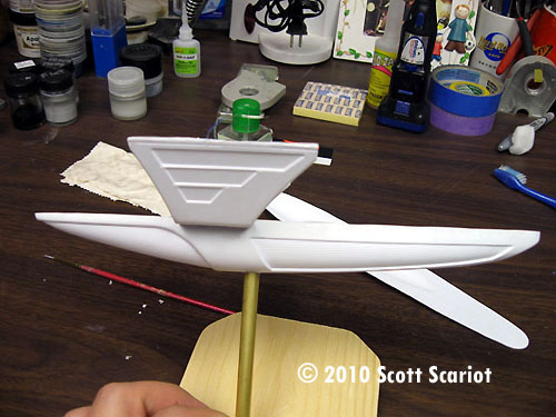
Day 10 Today I returned to sand the seams on the warp nacelles and the pylon. This was really easy to do. While I was sanding I decided to test fit the pylon to the main hull. I’m glad I did because I found out that the pylon is too long for each side of the main hull. So I marked how much of each side I would have to remove and then used a cutting wheel on my rotary tool to cut off the excess bits. The seams on the nacelles sanded down very well. To attach the nacelles to the main hull, I fed the wires through the holes in the hull I marked off where each nacelle should sit and then I glued them onto the top of the main hull. I made sure the nacelles were straight and I then I left the glue to set. |
|
Total work time: 1 ½ hours |
|
|
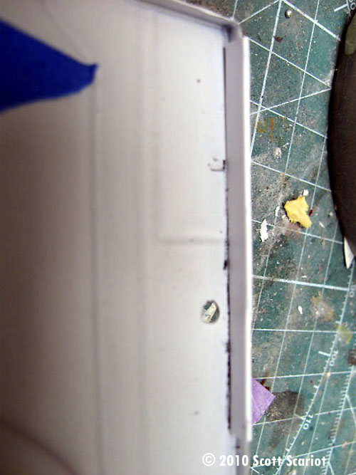
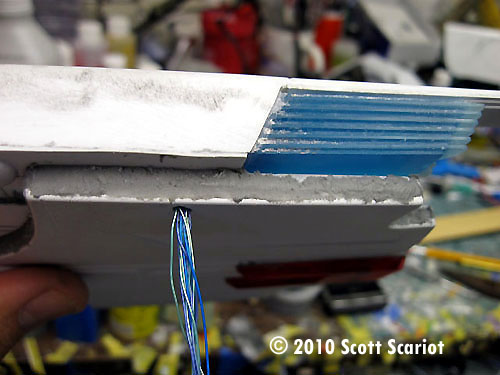
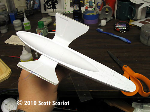
Image: Tabs to aid in gluing the hull halves |
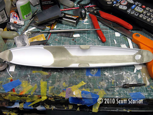
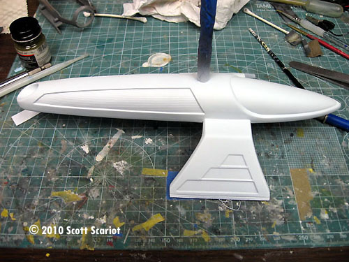
Day 11 With the nacelles on the model and all of the wires run I could now glue the two parts of the main hull together. I carefully scraped some of the paint off of the edges inside of the main hull. I glued some styrene strips into the bottom piece. Then I carefully threaded all of the wires through one side of the model so I could connect them to the power supply through the pylon. Once I had the wires in place I taped them down. When the glue on the tabs had set up enough I glued the two parts of the main hull together. I waited about ½ hour and then I mixed up some Fixit putty and began to fill the seam around the outside of the main hull, saucer and the nacelles. I put the model down to let the putty cure. Total work time: 1 ½ hours |
|
|
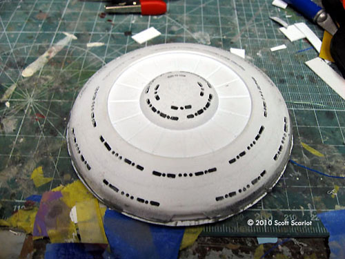
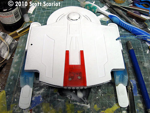
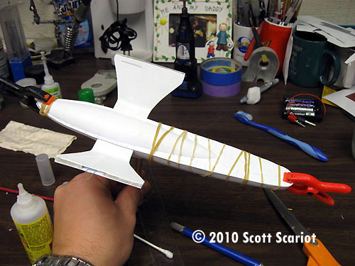
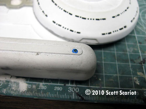
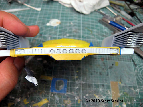
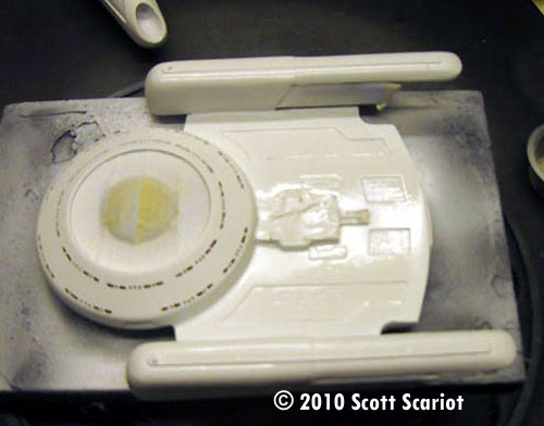
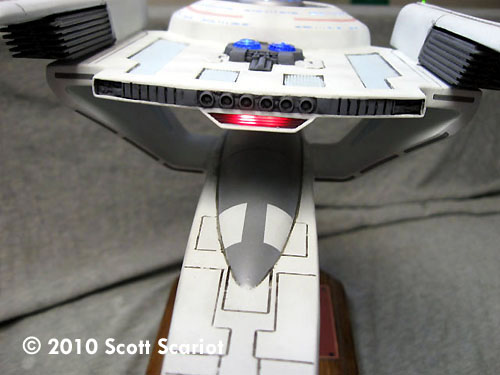
Image: Light check, underneath |
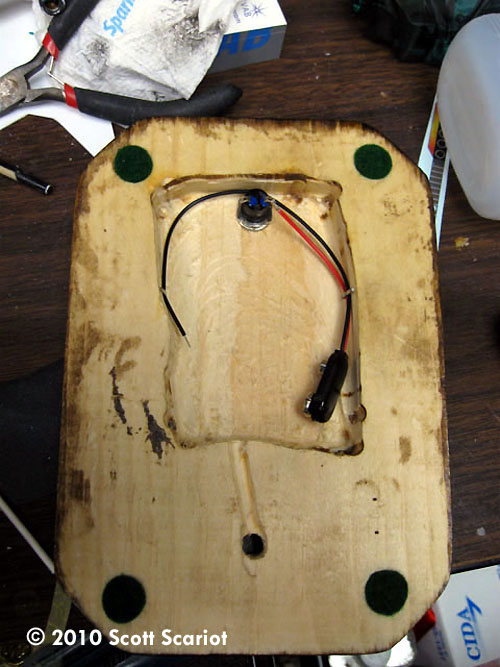
Day 12 I had a minor set back today. When I did a lighting test I found that the LEDS in the saucer had stopped working. I tried everything to get them to light up, nothing worked. I had to crack open the saucer to try and solve the problem. To open the saucer back up I tapped it on my desk lightly, which caused the seam to reopen. Then I used my hobby knife to pry up the rest of the saucer. Once I had the saucer open I did a test of the LEDS. They all seemed to be working but all three would not work in parallel. I checked the net and found an LED resistor calculator that showed that I didn’t have enough power to get all three LEDS to light up. So I used the calculator to figure out what kind of resistor I needed to use so that the LEDs would light up. Luckily I had the resistors I needed. I soldered the resistor to each LED individually and when I powered the lights every one came on! I taped all of the LEDs back to the bottom of the saucer. I used CA to reattach the top of the saucer to the rest of the model. I mixed up some Fixit and refilled the seam around the saucer. |
I had a little time so I picked up the bottom half of the secondary hull and I drilled a hole into the bottom of the part. I cut down a brass rod to attach the model to the stand. Then I cut two slits in the top of the rod and bent the parts down. I glued this into the bottom of the secondary hull. Total work time: 2 hours |
|
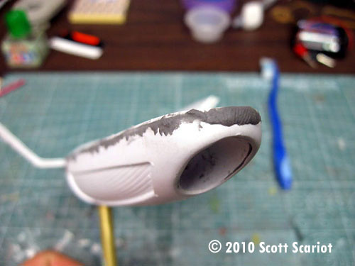
Image: PSR |
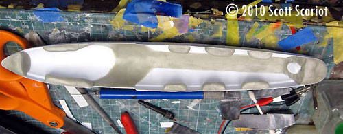
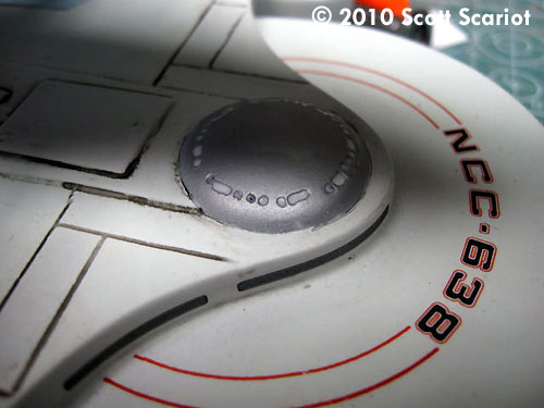
Day 13 Today I had lots of sanding to do, so I filled a small bowl with water and got out a sheet of 220 grit wet dry sand paper and got to it. I started to sand the seams along the sides of the main hull and then around the saucer. I did this till I had the seams sanded flat. Total work time: 3 hours. |
|
|
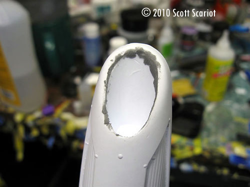
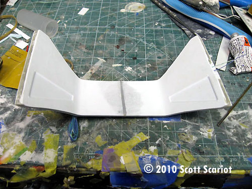
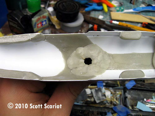
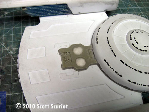
Image: Epoxy putty reinforces the inside of the secondary hull |
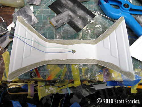
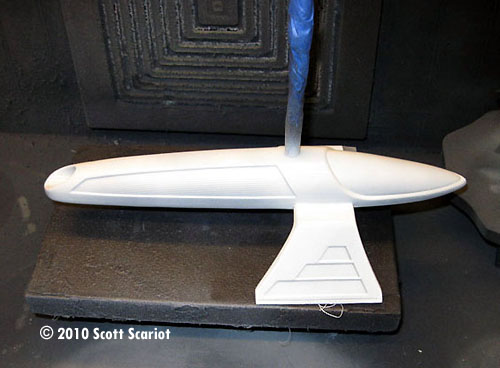
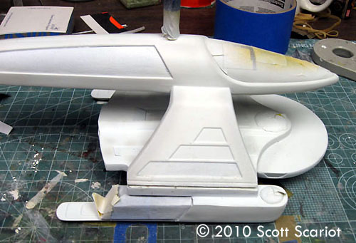
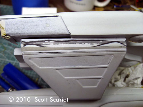
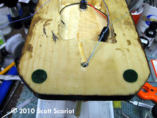
Day 14 With the seams sanded on the primary hull I needed to prepare the model for painting. I filled the impulse driver holes with bits of cotton. I cut some masking tape for the impulse engine, and I used liquid mask for the navigation lights on the nacelles. Now it was time to finish construction on the secondary hull. I placed the pylon part in the slots cut into the side of the bottom hull piece. I measured both side to make sure the pylon was centered. Then I tacked the part in place with some model cement. I did this just to hold the part in place. Once the glue and cured enough that I could set the part down I mixed up some 5 minute epoxy and I applied that around all of the edges of the pylon. I want to ensure that the pylon will not come loose, and it will support the weight of the primary hull. After the epoxy had cured I cut some crosshatches into the putty shelves I added earlier and I glued the top of the secondary hull on with CA. I used claps and rubber bands to keep the part secured. I left the glue to cure. Total work time: 2 hours |
|
|
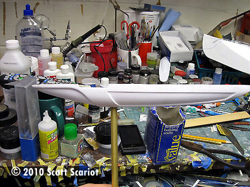
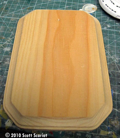
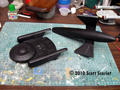
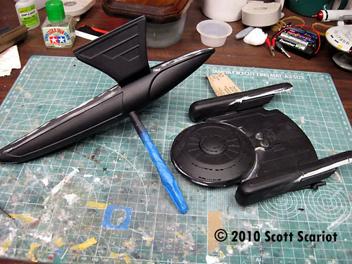
Image: Starting point |
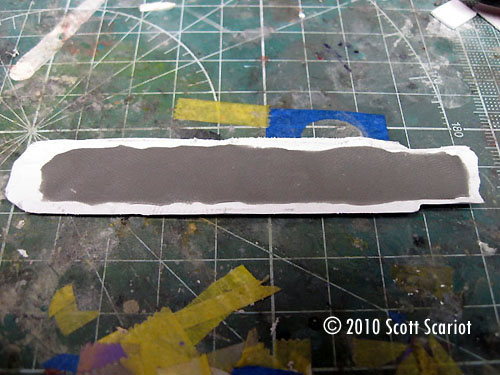
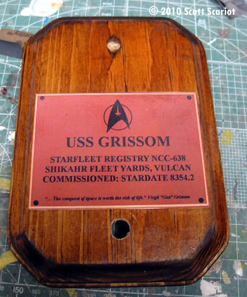
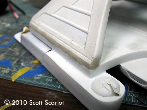
Day 15 I was able to sneak in a little extra model building today, because I had a later start to my work day. I removed the clamps and the rubber bands. I broke out the Fixit putty and mixed up some. Then I filled the seams around the top if the secondary hull and the pylons. I left the putty to cure and went to work. Tonight when I got home the putty and cured and was ready to be sanded down. Sanding the seams went fairly well; the biggest issue I had was an area near the pylon on the right side. The bottom and top pieces had separated and I ended up sanding a big divot in the side of the model. This ticked me off but all was not lost I just mixed up some more fixit and filled the divot. I used some water to smooth it out. I had some time so I picked up what will become my base, a pine plaque from Michael’s. I also printed out a dedication plaque to put on the base. I sanded down the plaque and I applied some stain. I waited a few minutes and then I wiped off the excess stain with a rag. Total work time: 3 hours (1 before work & 2 in the evening) |
|
|
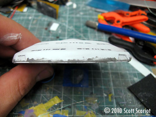
Image: Yesterday's patch rubbed down. |
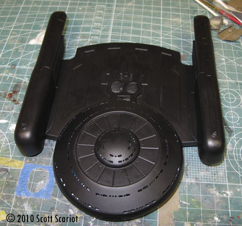
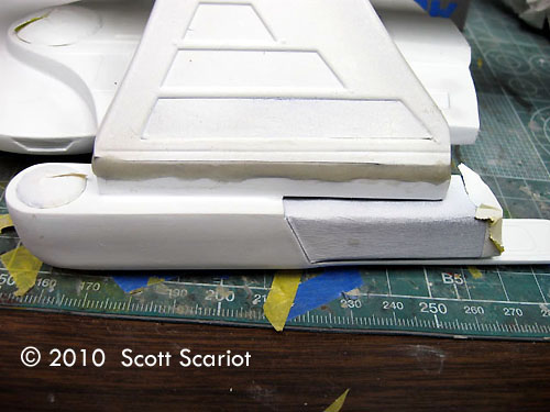
Day 16 Today I sanded down the patch I added yesterday. Then I cleaned the primary and secondary hulls with plastic prep. I sprayed the bottoms of the primary and secondary hulls with a coat of black Duplicolor automotive primer. Once the primer dried then I flipped the parts over and sprayed the tops. After the primer dried I picked up both parts and looked them over. I still had some seam work to do. I spread some gap filling CA on the seam and then sanded it down with 320 grit sand paper. Total work time: 3 hours |
|
|
Image: Plaque |
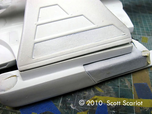
Day 17 I continued work on the seams today. When I looked closely at the pylons I saw more seams that needed filled so I applied more CA and sanded both sides of both pylons. I also cleaned up the seams along the rear of the primary hull near the JT Graphics resin piece. I also had to add some raised detail behind the Impulse crystal housing. I did this by cutting down some styrene sheet and a piece of styrene half rod. Once I thought I had all the seams filled I re-primed both parts. |
While the primer was drying I picked up the base. Now that the stain was dry I needed to finish working on it. I used a router to cut out a void for the battery. I drilled holes for the brass rod and the on/off button. I glued the dedication plaque on the base. Once the glue set I applied a coat of polyurethane to the base. Total work time: 2 hours |
|
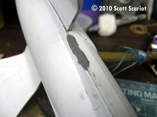
Image: Oh, yeah.... |
Day 18 After giving the primer time to dry I picked up both hulls and still found some minor seams on both hulls that had to be filled. So I broke out some more CA and applied it over the seams. This time I added a small bit of baking soda to speed the curing process. I also discovered that the area where the pylons enter the secondary hull. I filled these with Tamiya Basic putty. I also applied some Tamiya Basic putty to the rear of the primary hull in between the impulse engine and the rear resin detail part. I let the putty dry. After a couple hours I came back and sanded down the putty. I re-primed the two hulls and let the primer dry. After it did I checked both hulls and found some seams that still were visible! So more CA and more baking soda were applied to the seams, and then sanded down and both hulls were re-primed. Finally! All the seams had disappeared! Total work time: about 4 hours on and off through the day. |
|
|
Image: Secondary hull in the spray booth |
Day 19 After three days of dealing with seams it was time to start painting! I enjoy this part of modeling the most. The Oberth is mostly white, but it does have some paneling on it. It is not a full blown "aztec" found on other Federation starships, but it will make the model more visually interesting. I have learned to never paint white straight out of the bottle. It has a tendency to yellow over time. To prevent this I add a few drops of light blue paint to the white. If you use acrylic paint you can thin it down with blue window cleaner for the same effect. After I had the paint mixed up I fired up my Iwata airbrush. I sprayed a light coat on the bottom of both hulls. After that dried, I sprayed a light coat onto the top of the hulls. Once the paint dried I sprayed a second coat on the top and bottom of both hulls. Total work time: 2 hours |
|
|
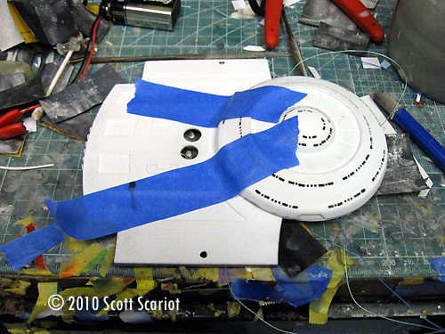
|
Day 20 Today I began the slow process of masking. This will have to be done several times for the various colors on the model. I decided to start with the dark colors and work to the light. Using low tack yellow tape I masked of the indented area on the saucer. I also masked of the rear of the saucer, finally I masked off the two indented areas on the side of the secondary hull. Total work time: 1 ½ hours |
|
|
Image: More grey |
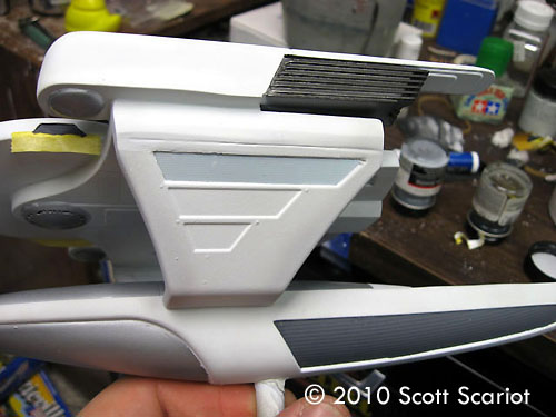
Day 21 With the model masked today I was ready to lay down some paint. I loaded up my Iwata airbrush with some Testors Model Master Gunship Gray paint. I lightly sprayed the masked areas till the color built up to where I wanted it. I left the paint to dry.Total work time: 45 min |
|
|
|
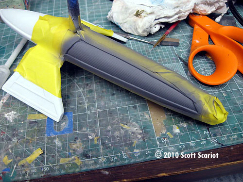
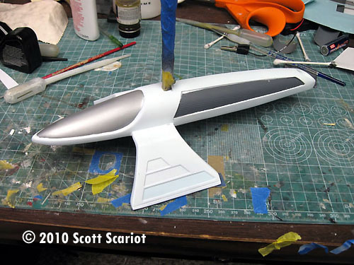
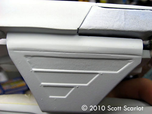
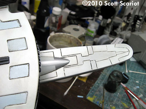
Day 22 Once the Gunship Gray was dry I began masking off the corrugated areas on the primary hull and on the pylons so I could paint them. Pictures of the studio model show these areas are a light blue. I took some of Testors Light Blue and lightened it with White until it was a nice pale Blue. I airbrushed the Blue on to model. I left the paint to dry. Total work time: 1 hour |
|
|
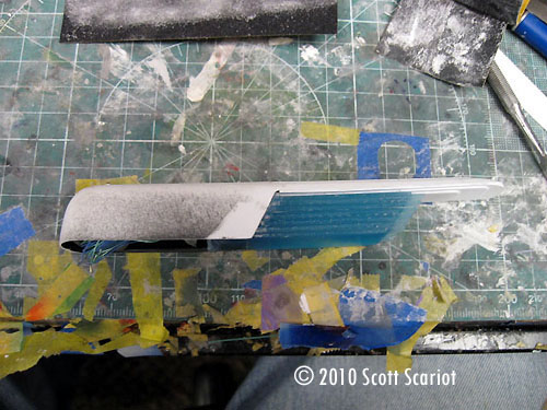
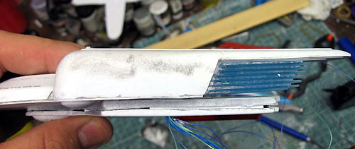
Image: Secondary hull |
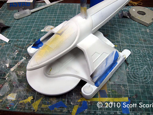
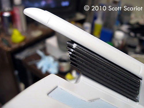
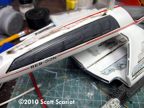
Day 23 Today I wanted to begin laying down the metallic paint. To give the warp Field Grilles a little “pop” I decided to paint them with Alclad II Steel. I masked off the warp nacelles and shot a light coat onto the model. I left the model to dry. I came back to the model after 30 minutes and shot another coat onto the model. I gave the model another 30 minutes to dry. Alclad usually dries very quickly but I just wanted to make sure the paint was really dry. While the saucer section was drying I picked up the secondary hull and began to mask off the top and forward parts so that I could spray a coat of Alclad Aluminum on to the model. After the secondary hull was masked off I picked up the saucer section and masked off the bridge done, the dome on the bottom of the hull and the domes on the bottom of each nacelle. |
Then I shot the model with a light coat of Aluminum. Since I was shooting the Aluminum over a light color I used very light coats and was careful to build the paint up slowly. That way I got a nice even color. After several coats of paint I was happy with the way the model looked I left both sections to dry. Total work time: 3 hours |
|
|
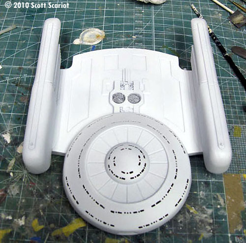
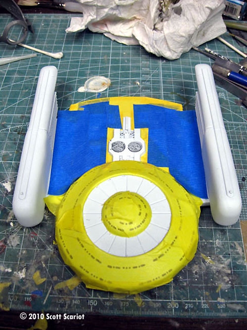
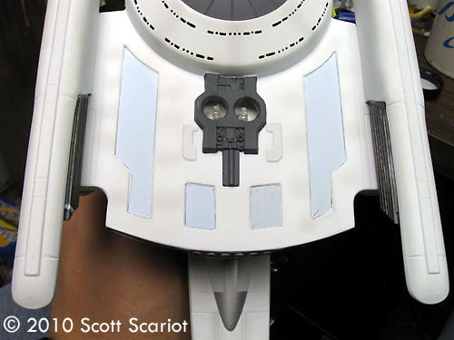
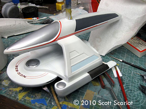
Day 24 I thought I was closing in on the finish line with this model when I took a look at my reference photos and I realized that I still needed to paint on some hull paneling. So I took some very low tack tape and I masked off all of the areas I had painted with the Alclad yesterday. I also masked off any other area on the model that was not white. Once that was done I sprayed both parts of the model with another coat of the white base color and left them to dry. Total work time: 2 hours |
|
|
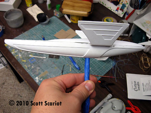
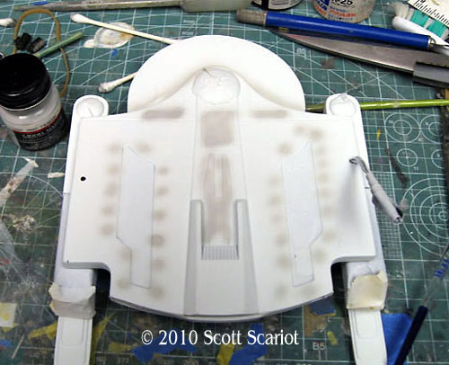
Image: Underneath |
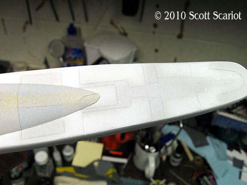
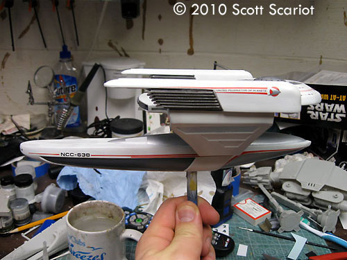
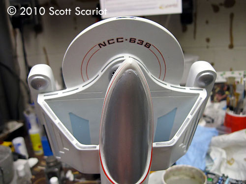
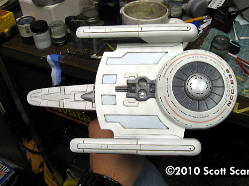
Day 25 Okay, so now I need to paint the hull paneling. I have two choices: I can carefully lay down tape and then spray the color remove the tape and then re-spray the model with the white base coat, or I can freehand the panels on and then re-spray the basecoat. I chose the latter. The panels aren’t real pronounced and I’m really just looking to break up the starkness of the white and make the model a little more visually interesting. To paint the panels, I lightly sprayed Testors Light Grey onto the areas that I was looking to darken. I let the paint dry, then reviewed my work. In a few spots I did add a few more panels. The after the second coat had dried I lightly re-sprayed the model with the white base coat. This gave the model the “right” look. Total work time: 2 hours |
|
|
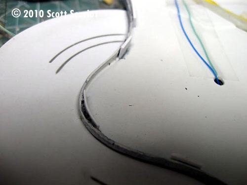
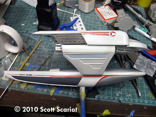
Image: Another look |
Day 26 I’m nearing a point with this model that I need to get it off of my bench because I’m tired of looking at it. Lucky for me I’m in the home stretch. With the panels painted I can connect the power supply and glue the primary and secondary hulls together. First I removed the tape from the power supply lines going into the primary hull. I connected them to a battery to perform a quick check just to make sure the LEDs were working. They were, so I disconnected the battery. I usually leave the wires a little long so that way I have enough to attach them to the power source. I trimmed the wires down and attached them to the wires in the secondary hull. I did another quick power check - the LEDs fired up again. I fed the wires down into the pylon on the secondary hull. |
To attach the two hulls to one another I mixed up some 5 minute epoxy. I applied it to both pylons. Due to the size and awkward shape of the two parts I had to hold them in place while the epoxy set. Once the epoxy had set enough that I could let go of the parts I put some tape over the seams just to make sure the parts didn't move. Total work time 1 ½ hours |
|
Image: Wow. |
Day 27 Tonight I removed the tape from the joints. There were some pretty big seams on each side that needed filled. So I broke out the Aves and mixed up a batch. I then filled and smoothed the seams. Once the seams were filled I set the model down so the Aves could cure. Total work time: 1 hour |
|
|
|
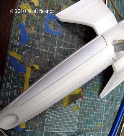
Day 28 Today I wet sanded the Aves on the outside of the pylons smooth. Then I used a small round file to sand the Aves on the inside of the pylons. The inner seams didn’t need a lot of attention because I had smoothed the putty while it was still wet. The seams on the front and back of both pylons were a little rough. So I wet sanded these areas with finer grits of sandpaper. This helped to knock down the seams and smooth the area out. There was one area on the rear of the right pylon that was indented just a little more than the other three. I probably just trimmed too much plastic off when I cut the part out of the sheet. So to fill the area I used a little bit of Tamiya grey putty. I let the putty dry for a couple hours. Once it did I sanded it smooth. This evened out the area. Total work time: 3 hours on and off |
|
|
Image: This area is a little rough. |
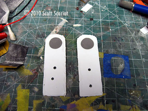
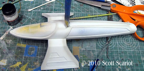
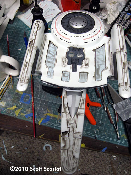
Day 29 With the putty cured, I sanded it down and then sprayed the putty with the base color. Once the paint dried, I began removing the masking tape. Once I had all of the tape removed I found a few areas that needed touched up, mostly from paint running under the tape, or overspray - but most of the areas looked pretty good. To clean up the edges I just used a fine tipped paint brush and as steady a hand as I could. I also realized that I needed to paint the shuttlebay doors, so I painted each door Gunship Gray. I touched up a couple more areas on the model here and there. I believe that the model is ready now for gloss coating. Total work time: 2 ½ hours |
|
|
|
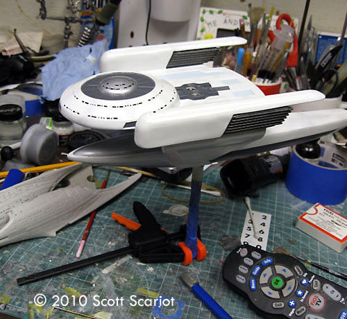
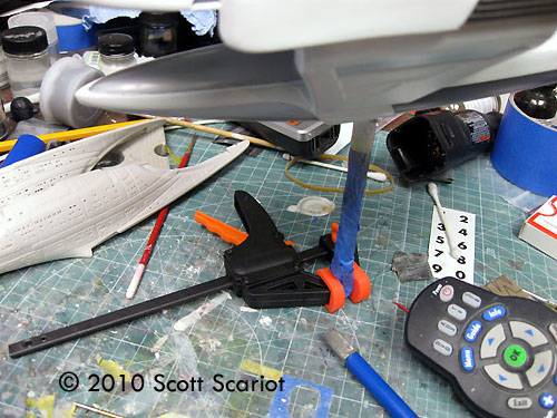
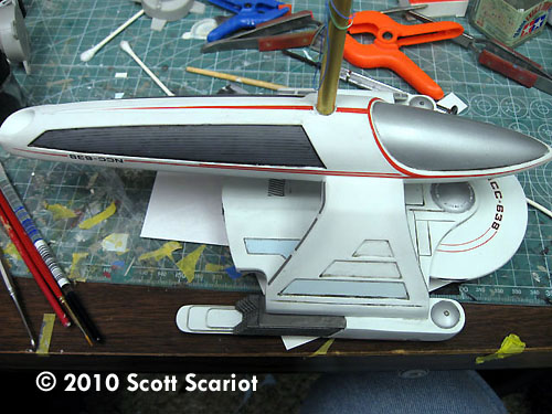
Day 30 Today I was indeed ready to begin gloss coating the model. I sprayed the models bottom with Future. I would allow the Future to dry for 20 or 30 minutes and then I would spray another coat. I continued this process until I had a nice smooth shine. When it was time to spray the top of the model I had a minor issue on how to do it since I had already attached the brass rod to the bottom of the model. The solution was very simple: I attached a bar clamp to the bottom of the brass rod to act as a foot. It worked quite well. So I coated the top with several coats of Future. Once I was satisfied with the sheen I left the model to sit overnight. Total work time: 3 hours on and off |
|
|
Image: In progress |
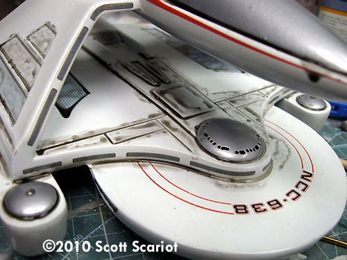
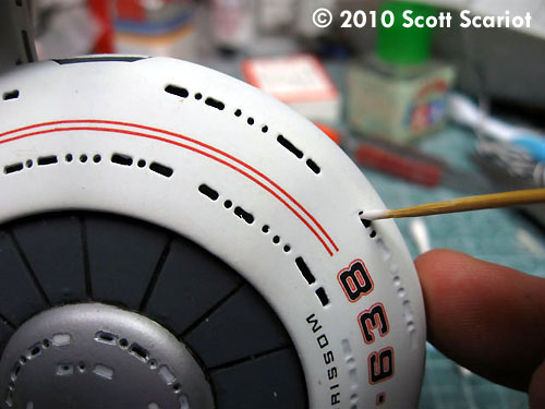
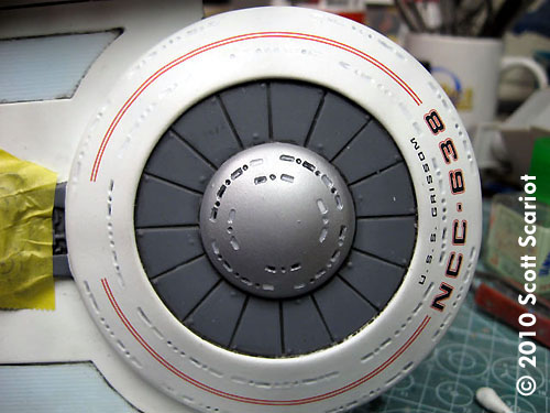
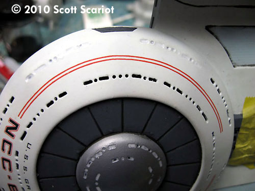
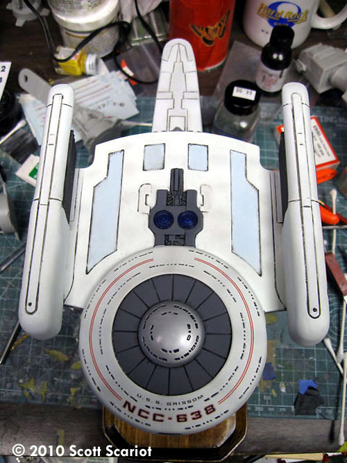
Day 31 Today was all about applying decals. So I settled it to the work bench with a cup of hot water and my JT Graphics Oberth decal sheet. I had applied a light coat of Micro Mark liquid decal film to the decals a few days before just to add a little strength. I started in the bottom of the model I applied the registry and stripes to the bottom of the saucer. The biggest challenge I had with the decals was with the two red stripes on the side of the secondary hull. This was because of the odd shape of the decals to make application easier I had to cut the swoop off the decals. This made the decal easier to apply. I applied the swoop later and was able to get the decals positioned so that the cut is almost undetectable. I also had to modify the pennants for the warp nacelles. I cut of some of the bottom stripe so that the decal would better fit the nacelle. I had some minor tearing on the registry on the top of the saucer, but I was able to get that fixed pretty quickly. Once all the decals were on I applied a little setting solution to the top of the decals and set the model aside. |
Total work time: 4 hours |
|
Image: Future seals the decals |
Day 32 With the decals on the model I am now in the home stretch. Today I sprayed several coats of Future onto the model. This second coat of Future will protect the decals and will give me a nice smooth surface on which to to apply a wash. While applying the second coat of Future I noticed a nick on the top of the bridge dome. It stuck out from the Alclad. I knew I had to do something about it, so I got out the bottle of Alclad Aluminum and I lightly re-sprayed the dome until the nick could no longer be seen. I let the Alclad dry and then I sprayed the dome with Future to protect the finish. Total work time: 1 hour |
|
|
Image: Wash going on |
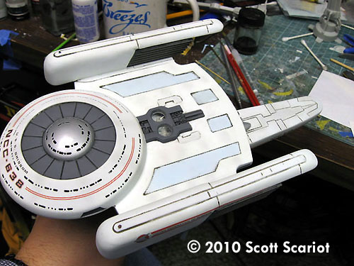
Day 33 After allowing the second coat of Future to dry overnight I sat down to begin washing the model. I used to hate washes. I could never get them to look right. However,a member at my IPMS club showed me how to make a sludge wash. You take 1 part dish soap and 3 parts water then add a little Tamiya paint for color. The stuff goes on like a dream! It settles in the panel lines nice. Plus since is just water, soap, and acrylic paint it can't harm the model. If you make a mistake it comes right off. Anyway, using a fine tipped brush I applied the wash to the top of the model. I set the model down and let the wash dry. When I came back I used a damp Q-Tip to remove the excess wash. I needed to re-apply the wash to a couple areas but most took it very well. The second application worked well. Once the wash on the top of the model was done I flipped the model over and applied the wash to the bottom of the model. This was a little more difficult to do because of the tight space in between the primary and secondary hulls. Once the wash dried I used a longer medical applicator with a wooden handle to remove the excess paint. The indented grey areas on the secondary hull needed two applications of wash to get it too look right. With the wash done I set the model down for the night. |
Total work time 2 ½ hours. |
|
Image: Matte clear coat on the model |
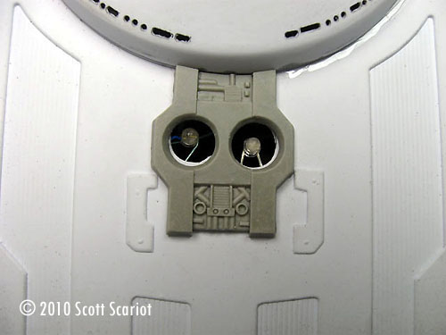
Day 34 Today I began flat coating the model. I used a low pressure and sprayed light coats on the top of the model. I left the aluminum areas glossy. Once the entire model had been flat coated I glued the two resin impulse driver crystals into place. I taped them down and began to fill the windows with Micro Scale window maker. I used a toothpick to apply a drop of window maker to each window. I started with the dome on the bottom. Once those windows were filled I moved to the top of the model. I did the windows on ½ of the model and then I did the windows on the opposite side. I removed the masking tape from the brass rod. I set the model aside while the windows dried. I began to wire a 9V battery clip into the base. I used two staples to hold the clip into place. I twisted the wire around the switch to prepare the switch. Total work time: 4 hours |
|
|
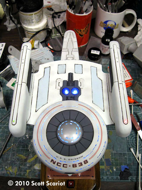
Image: Brass rod in the base |
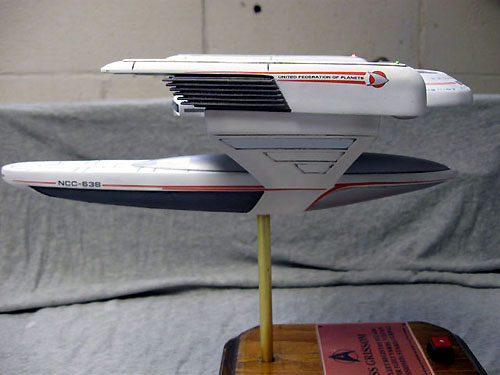
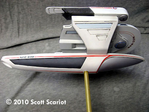
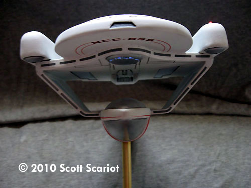
Day 35 With the windows done the model was just about complete. I gave the impulse crystals a quick wash. Then I mixed up some epoxy and I applied it inside the hole in the base. I ran the wires down through the hole and twisted the rod into place. I used the rest of the epoxy to secure the wires in a trough I cut into the base. Once the epoxy set I trimmed down the wires and soldered them to the switch and the battery clip. When I pressed the switch the lights came on. With that the model was completed. Total work time: 2 hours Wow! This was a fun project. It was different; the model did take a little longer than I thought it would. But, I am so happy with the way it looks. I’m really glad that the resin detail parts for this kit are available. They add so much to the model, and made construction much easier. This is the second time I have built this kit and it really did come out looking better this time than my first go round. I also like the size of the model. I know that at 1/537 scale it is a bit of a scale orphan now but, I think the size of the model is just right. I have the 1400 scale version of this ship and it’s tiny. So, this model gives more to look at. I have always liked this design and I’m glad I have this model to add to the shelf in my model room. If you can get one of these models I really recommend getting and building one. |
|
![[[Battlestar Galactica models & more at the Starship Modeler Store]]](http://www.starshipmodeler.com/resource/bsg_ad_1.jpg) |
| Visit our sponsors! | Advertise with us |
![]()
This page copyright © 2010 Starship Modeler™. Last updated on 15 September 2010.
![[Please click to enlarge]](olb/ss_oberth/01_partscutoutofthestyrenesheetsDay1.jpg)
![[Please click to enlarge]](olb/ss_oberth/03_RedResinImpulseenginewithtworedLEDSDay3.jpg)
![[Please click to enlarge]](ss_oberth/03_BlackprimerlightblockDay3.jpg)
![[Please click to enlarge]](olb/ss_oberth/04_BottomprimaryhullwiredDay4.jpg)
![[Please click to enlarge]](olb/ss_oberth/05_Shuttlebayinsertsday5.jpg)
![[You know what to do]](olb/ss_oberth/06_Internalsupportandgluetabsday6.jpg)
![[Please click to make big]](07_insideofsaucerDay7.jpg)
![[Click to enlarge]](olb/ss_oberth/08_Innerconefilledday8.jpg)
![[Please click to enbiggen]](olb/ss_oberth/09_nacellepartssandedsmoothandcrosshatchedday9.jpg)
![[It gets bigger by clicking...]](olb/ss_oberth/10_Nacellesattachedtotheprimaryhullday10.jpg)
![[Please click to enlarge]](olb/ss_oberth/11_BottleofCAforweightontheprimaryhullassemblyDay11.jpg)
![[Please click to enlarge]](olb/ss_oberth/12_Lightcheckafterrepairday12.jpg)
![[Please click to enbiggen]](olb/ss_oberth/13_Nacelleseamsandedday13.jpg)
![[Please click to enlarge]](olb/ss_oberth/14_PyloninplaceDay14.jpg)
![[Please click to enbiggen]](olb/ss_oberth/15_Dedicationplaqueday15.jpg)
![[Please click to enlarge]](olb/ss_oberth/16_Primeredpartsday16.jpg)
![[Please click to enlarge]](olb/ss_oberth/17_detailaddedday17_lil.jpg) >
>![[Please click to swell]](olb/ss_oberth/18_seamsgoneday18.jpg)
![[Please click to enlarge]](olb/ss_oberth/19_basecoatday19.jpg)
![[Please click to enlarge]](olb/ss_oberth/20_secondaryhullmaskingday20.jpg)
![[Please click to enlarge]](olb/ss_oberth/21_Gunshipgrayday21.jpg)
![[Bluer than Blue]](olb/ss_oberth/22_lightbluepanelsday22.jpg)
![[Please click to enlarge]](olb/ss_oberth/23_fieldgrillesDay23.jpg)
![[Please click to enbiggen]](olb/ss_oberth/24_remaskingday24.jpg)
![[Please click to enlarge]](olb/ss_oberth/25_Detailday25.jpg)
![[Please click to enbiggen]](olb/ss_oberth/26_2hullsjoinedday26.jpg)
![[Please click to enlarge]](olb/ss_oberth/27_closeupofthegapday27.jpg)
![[Please click]](olb/ss_oberth/28_Tamiyagreyputtyfillingagapday28.jpg)
![[Please click to enlarge]](olb/ss_oberth/29_shuttlebaytouchupday29_lil.jpg)
![[Please click to enlarge]](olb/ss_oberth/30_shinyday30.jpg)
![[Please click to enlarge]](olb/ss_oberth/31_topfrontviewdecalsdoneday31.jpg)
![[Please click to enlarge]](olb/ss_oberth/32_AviewoftheBridgedomenickgoneday32.jpg)
![[Please click to enlarge]](olb/ss_oberth/33_undersideafterwashingday33.jpg)
![[Please click to enlarge]](olb/ss_oberth/34_Flatcoatrearday34.jpg)
![[Please click to enlarge]](olb/ss_oberth/35_saucerday35.jpg)