
|
The projects in this section are presented as step-by-step journals. Our intent is to delve deeper into the nuts and bolts of constructing and finishing a particular project while giving a sense of how long it takes. The subjects will range from simple kits to complex dioramas and everything in between. Authors will range in skill level, and include hobbyists and professionals. If you have a project you would like to share here, please drop us a line to discuss it. |
| Star Trek® USS Voyager |
|
Project type: Kit with electronic components
by Simon Mercs - images & text © 2003 This project documents the construction of a standard kit with a lot of custom electronics added. The kit used was the standard Revell-Monogram USS Voyager offering provided by the client. You can see more of Simon's work at his website: www.thekitfactory.com - Ed. |
|
Day 11 | Day 12 | Day 13 | Day 14 |
|
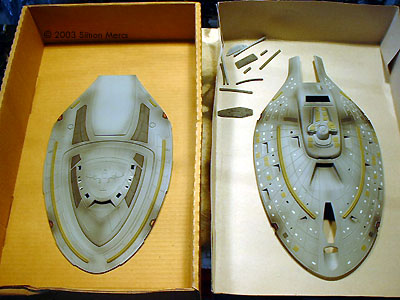
Image: Saucer halves, freed from the sprue |
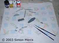
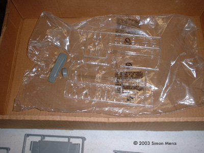
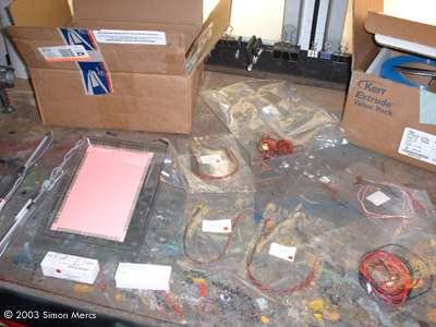
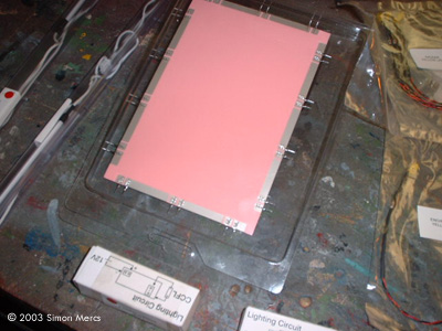
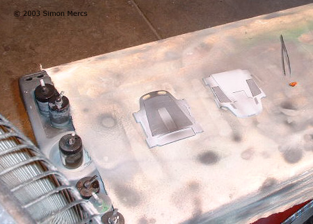
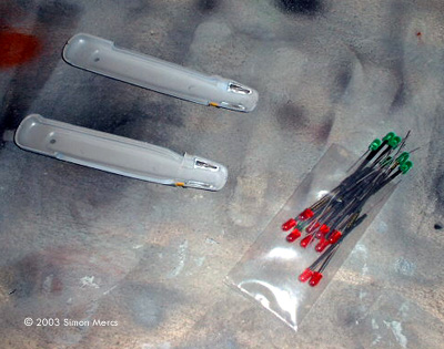
Day 1 The kit finally arrived today. The shop was set up to accommodate a large project in several sections: preparation, electronics, and paint. Assembly and electronics tests will come later. At this point, the entire kit was checked for flaws or missing parts. The electroluminescent sheet material I will use is plainly seen on the electronics table. In its "off" state it is pink, but glows bright white when powered. The tiny fluorescent tubes are encased in their protective plastic containers. These are a shade of "Royal Blue". There are still components due in the next day or two Trimming, sanding, puttying, cutting fingers - all start now. This is the dull part of the process but it is the foundation of a fine piece of modeling. Today's time consumption for this project is about 3 hours. I have 2 others presently being worked on as well. |
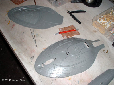
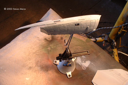
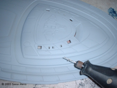
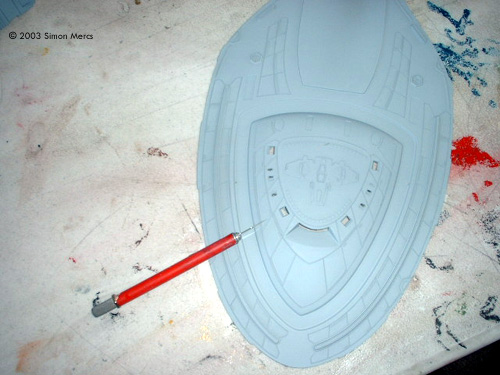
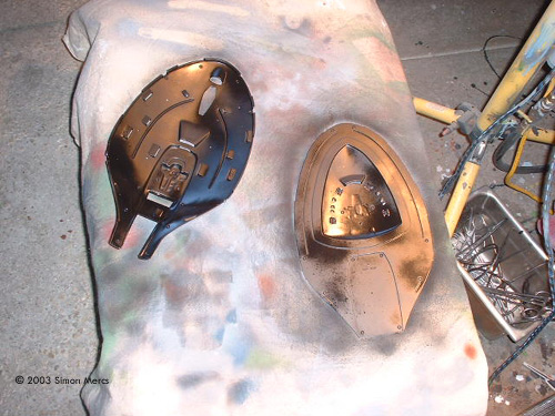
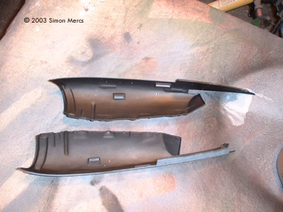
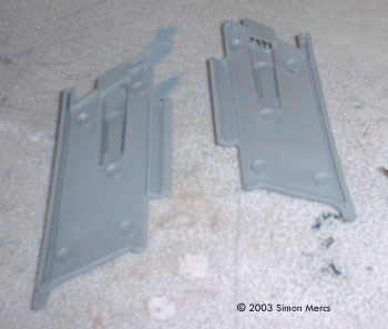
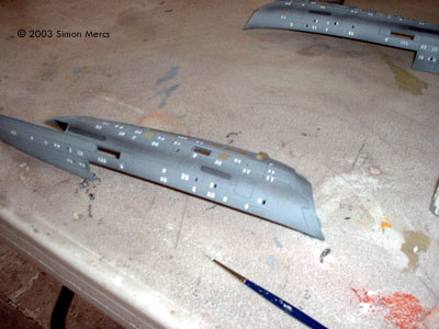
![[Click to enlarge]](sm_v/sm_voy17.JPG) ^ Floodlamps help speed the paint's drying time Image: Secondary hull half, drying on a stand Image: A motor tool was used to rough out the window shape, Image: ... which was then finished with a hobby knife |
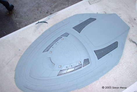
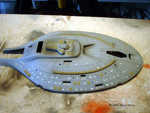
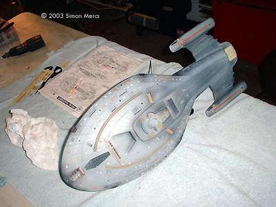
Day 2 Today the primary paint coats were applied to the hull. I am using a Light Gull Gray as the base color, Gunship Gray for the Aztec details, and an intermediate Brown for some of the plating colors. All are Testors' Model Master enamels. Three coats of Flat Black were also applied to inside surfaces as a "light block", and sealed with a dullcoate finish. The windows were cut out with a Dremel moto-tool, and finished by hand with an hobby knife. I only illuminate about 30% of the windows, which I feel provides a more realistic look. I've never seen every window lit up in show sequences; less is more effective, in this case. I started to apply the primary hull details by hand, although some will be done by masking and airbrush. The time spent today was about 8 hours.
Image: Painting the interior flat black will prevent light from shining through the kit's grey plastic |
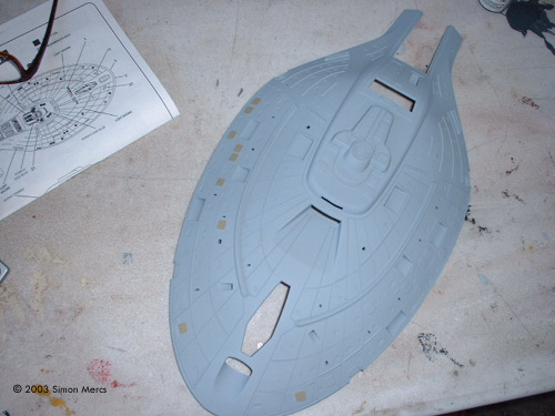
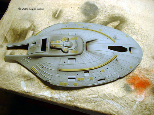
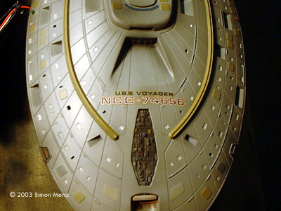
![[Click to enlarge]](sm_v/sm_voy41.JPG) ^ Painting details on the upper saucer half Image: Underside of the saucer Image: Saucer halves, detail painted Image: Basic weathering applied Image: Painting the unlit windows Image: Saucer top, before decals |
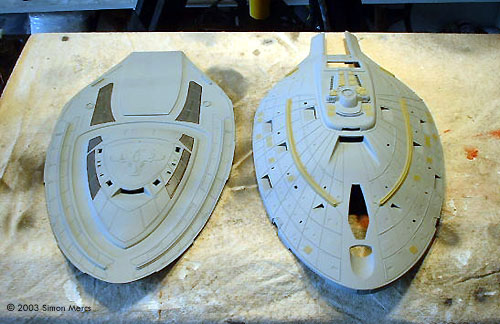
Day 3 On day 3 I'm beginning to really concentrate on the exterior hull features and details. The entire kit will be painted and detailed before electronics are installed during the assembly stage. This is how it's done in the studios and here at the Kit Factory. The windows which will not be lit were painted white. The Aztec tile features are in Gunship Grey and Sand/Desert Tan. The weathering effects are also put on at this point. This prevents overspray on clear parts and decals later. I use the minimum decals; I paint whatever I can rather than use decals or transfers. So far all the correct colors have been applied to match the studio prop version. Time consumption today, about 7 hours at this point ... but I'll probably work another 3 or 4 before I quit for the day. |
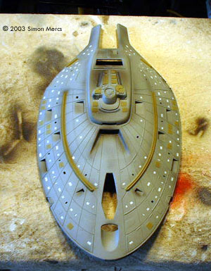
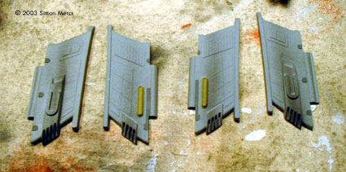
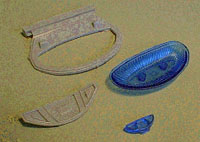
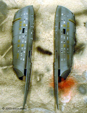
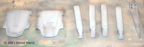
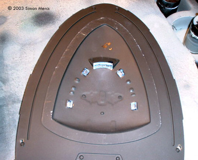
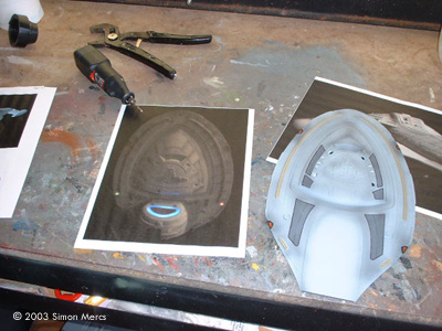
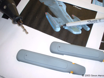
![[Click to enlarge]](sm_v/sm_voy66.JPG) Image: Underneath the saucer, painting details Image: The saucer halves and associated insert pieces are done, for now Image: Drilling out the grilles in the warp nacelle pylons Image: Pylons painted and weathered Image: The aftermarket deflector set I'll be using Image: Engineering hull and warp nacelle pylons, painted and weathered Image: Painting the unlit windows Image: Closer look at the Engineering hull halves |
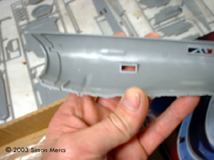
Day 4 I am continuing to work on outer hull enhancements. The Engineering section now comes into play. Windows and tiling effects were applied. The warp engine pylons need to be modified to allow a small red LED to illuminate the intake. The Monogram kit has several errors like this. As mentioned before, I also had to order a aftermarket sensor array that was clear blue, rather than try to chip away at the solid Gray Monogram-supplied part. On the pylon however, no such part exists, so we dig! One good point though, there is a bit of a "compartment" space in this part, big enough to sneak an LED in there and pass the power wires for the engine lighting through. The "weathering " effects were also applied at this point. The clear parts that will be spread out everywhere prevent us from doing this later. Pre- or post-painting is all in the requirements of the project or personal preference. I prefer pre-painting, but not every time. As I wrote this I was at about 5 hours already; I would go another 3 or 4 to give a 8-9 hour day. |
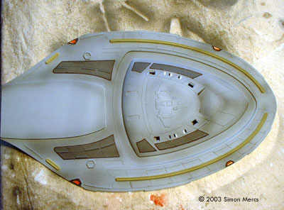
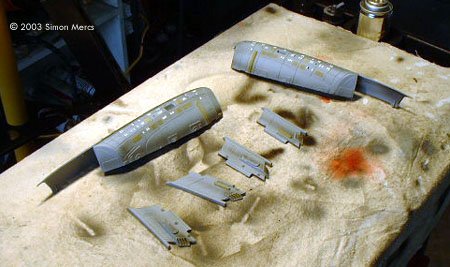
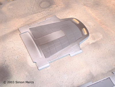
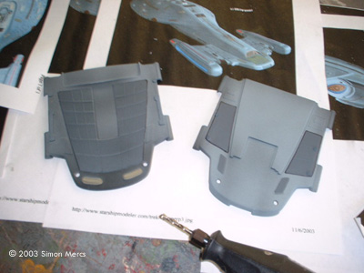
 ^ Time for detail painting on the smaller pieces Image: Painting and weathering the engine and shuttle bay pieces Image: Sensor strips detailed Image: Detailing the rear decks Image: Underside |
Day 5 The fine details are being applied to the small sections that are recessed on the hull ring. The clear parts will be affixed after all the paintwork is done. The engines and rear shuttle landing area have been "weathered" to blend with the rest of the kit. Next, I will apply detail tile work on the rear landing area as well as the needed work on the remaining parts. Assembly with lighting is just around the corner at this point! I have been up since 5am and am about 7 hours into it today; I figure I'll work another 3-5 until I'm pooped out. |
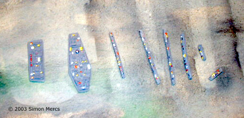
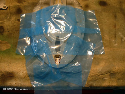
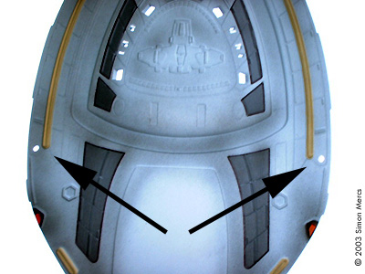
![[Click to enlarge]](sm_v/sm_voy112.JPG) ^ Drawing in the pattern on the sensor array Image: Masking off the pattern Image: Sensor pattern painted Image: Warp nacelles get detailed |
Day 6 A lot of time was spent on"little details" today. The top side sensor array has an interesting brown "grid" design on the real prop. Since it's added after the main paint application, some "blending" with the airbrush is required, subtle but effective. You can see the file photo on the workbench on a few shots (from Starship Modeler of course!). The last of the few important details are being finalized today along with the engines, and some early drilling of holes for the later installation of lighting. It's kind of like chess, you have to think many moves ahead of time. The drilling will continue into tomorrow. Hopefully we will see some lighting tests in the next few installments. Time spent today, about 7 hours. |
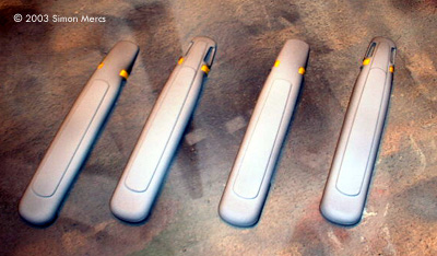
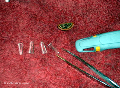
![[Click to enlarge]](sm_v/sm_voy132.JPG) ^ Installing clear bits Image: Bussard scoops, trimmed .... Image: ... and fitted. Image: Windows in place on the lower saucer half Image: Measure twice, cut once |
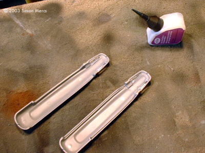
Day 7 The primary hull details and windows are now being applied. I use a special "Clear Drying" cement by Testors to make sure no "fog" clouds these parts. The hull perimeter inserts that line the outer edge were also glued in. All pre-drilling for the navigation lights (LEDS) has been completed according to file photos of the real prop I have - you gotta do your homework before you slice and dice. The engines are almost ready for lighting components, as well as the engineering hull. We are into pre-lighting/assembly now. The next phase is about to start. Image: Holes drilled for the lower saucer's nav beaconsImage: Marking the spots for the warp nacelle beacons Image: Holes drilled for those on the stern Image: Getting ready for the next phase |
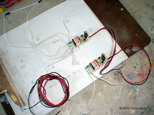
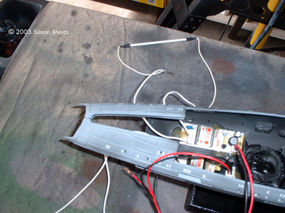
![[Click to enlarge]](sm_v/sm_voy150.JPG) ^ A multimeter helps me troubleshoot, to find out why something does not work Image: Here I'm wiring the transformers for the mini-flourescents that will light the warp nacelles. Image: Adding the electroluminescent sheet deflector lighting to the circuit. |
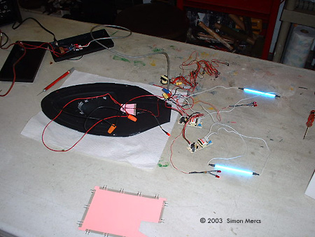
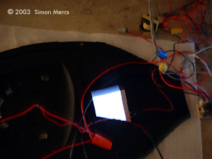
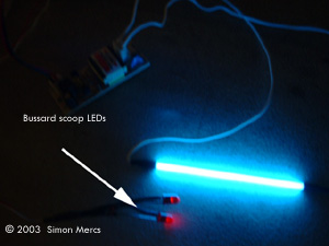
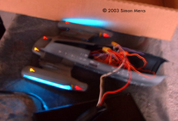
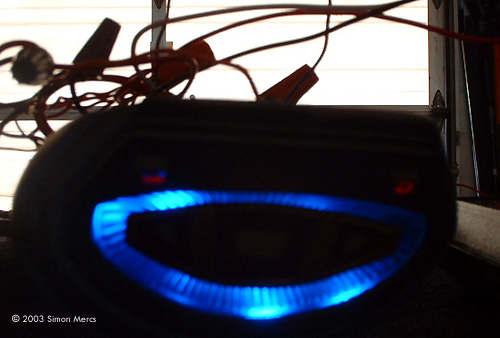
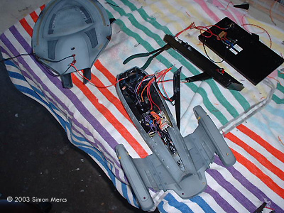
Day 8 Light tests are underway today. Light tests are needed right before actual assembly to make sure all the electronics will function correctly after the assembly stage. I'm still waiting on some very small LEDS for my navigation markers. The electroluminescent sheet material works nicely and has a blue cast. This may speed the assembly process up, since it will not require blue gel to 'color' the light; we will see. The bright red LEDS will light up the bussard scoops and the forward engine compartment. The electroluminescent sheet material will illuminate the sensor area and various portholes and windows inside the structure. Time spent today - 9 hours. Image: So far, so goodImage: electroluminescent sheet in action Image: Nacelle lighting |
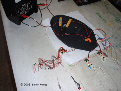
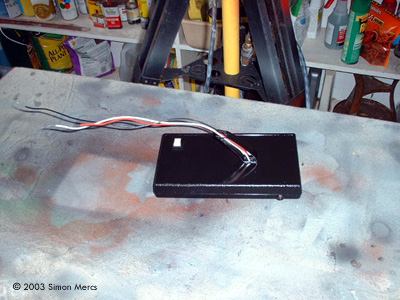
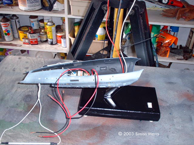
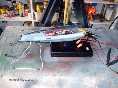
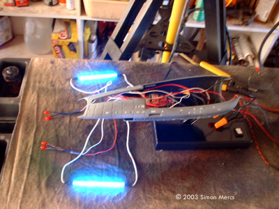
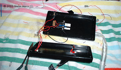
![[Click to enlarge]](sm_v/voy177.JPG) ^ The transformers/ballast for the flourescents were epoxied securely in place in the engineering hull Image: The base I made holds the power supply Image: Here I've started wiring components Image: The flourescents for the warp engines are wired ... Image: Followed by LEDs and the electro-luminescent panel for the deflector Image: So far, so good Image: The space inside the engineering hull is rapidly filling up Image: As you can see, the deflector is just too darn dim |
Day 9 Live and learn, that's today's operative word. The electroluminescent sheet material causes problems in this set-up. As this is a "real life" building project, stuff happens. A few problems with this material has made me remove it from the lighting array. One, theelectroluminescent sheet I obtainedhave an operational life of only 400 hours, not long enough for my prop. Also, the light is not bright enough to correctly simulate the Sensor Array.There is also a heat problem as this system requires a large resistor to be installed, and it gets very hot! Not advisable in a plastic shell. I had not used electroluminescent sheet material before and was curious at what it could do. Warning to other modelers, stick with LEDS, Diodes and Fluorescents, they are dependable and long-lasting. In a studio filming enviroment electro-luminescent sheets could be useful, but in a prop designed not to be serviced for years, useless. I have ordered more stable lighting to complete this project. I worked on the rest of the internal wiring today. No soldering, but some wire lengths were determined, and engineering hull internals locked in. From the photos you can see that the basic layout for the ship is there. The engines, the red engine details, the red weapons banks, with just some white lighting, and LEDS grouped around the Sensor Array with a blue lens to top it off. I'll add some navigation lights, tiny green (for the port side) and red (for starboard) LEDS that should arrive any day. Light tests occur all the way through the build. Remember, once the kit is completed, the lights better work or else all that effort is in vain. My next steps will involve final soldering of all leads, assembly of engines and saucer section including lighting, and last but not least, decal application. Not to get ahead of myself, these last few task will take a few days and the parts are not here yet. Time spent on today's work: 7 hours. |
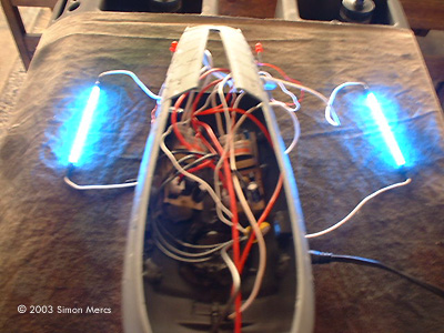
![[Click to enlarge]](sm_v/sm_voy204.JPG) ^ Mini flourorescent bulb lights the warp grilles Image: Nav light |
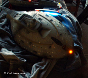
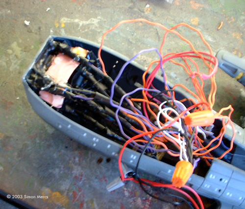
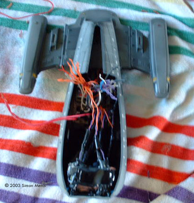
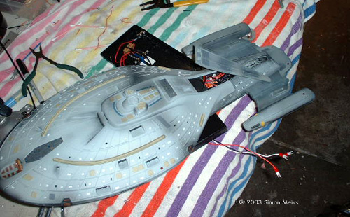
Day 10 All lighting for the engines, plus the navigation lights installed today. Much of the engineering section is complete except for forward sensor array, which is on order. A mess of wires has been tamed into a bundle I can position in the engineering section. The saucer section waits for its blinking Navigation lights. About 10 hours went into this session. Very productive day! Image: Wiring, tamedImage: Rear of model, lit Image: Top view |
![[Click to enlarge]](sm_v/sm_voy248.JPG) ^ Soldering connections |
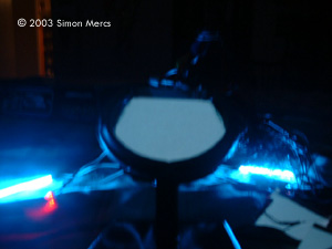
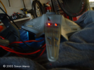
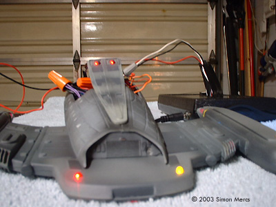
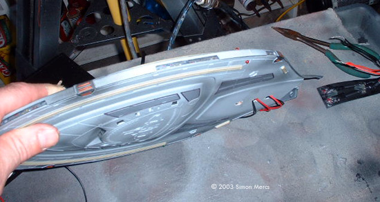
Day 11 As I await the special order "blinkers" for the saucer section, I worked on light leaks and structural integrity today. Also installed rear photon torpedo lights and the saucer prow navigation marker light. Light tests were conducted through each phase to fix any problems before final assembly. Time spent today, about 7 hours. Image: Bow nav light works ....Image: ... torpedo lights do too ... Image: ... and the engine lights still do. Bonus! |
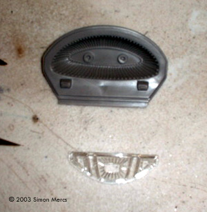
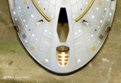
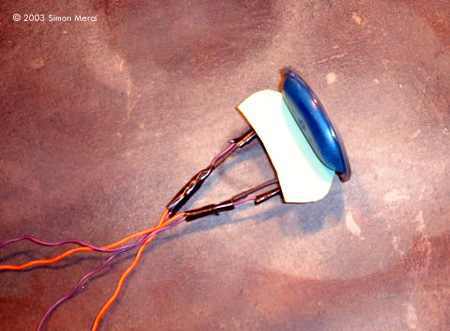
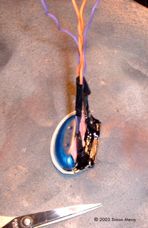
![[Click to enlarge]](sm_v/sm_voy262.JPG) ^ Deflector dish painted and ready for lighting Image: Two small red LEDs affixed Image: Electrical tape secures the wires, and painted epoxy keeps light where it's wanted |
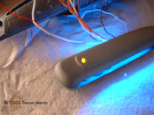
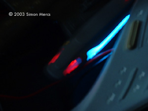
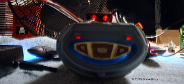
Day 12 Still waiting on those special order lights. But, the after-market sensor piece came in! Assembly of these components is compete except for the blue LEDS that will light up the sensor array in a tight oval cluster. Finding and fixing light leaks in the saucer section continues. Edges are tested and filled with epoxy, then over-painted with flat black. This will prevent those little light rays from seeping out, ruining the illusion. Time spent today, about 6 hours. Image: Deflector array installedImage: It's getting really crowded in there .... Image: LEDS work (the deflector dish itself is not yet lit) Image: Nav lights and photon torpedo launcher LEDs work |
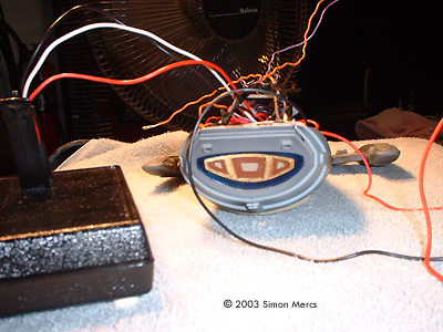
![[Click to enlarge]](sm_v/sm_voy283.JPG) ^ Running the nav lights Image: They work! Image: Deflector array, all lit up Image: A lightbox contains and amplifies the glow from the blue LEDs Image: Not a lot of room left in Engineering .... |
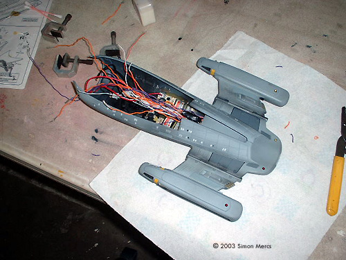
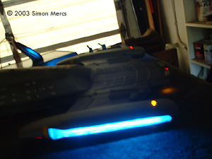
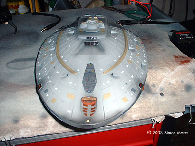
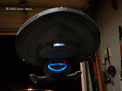
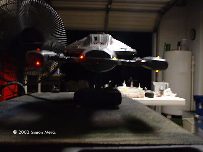
Day 13 Final assembly and lighting installation are underway today. Blinking Strobe LEDS have been used to accent the saucer's navigation lights. Internal lighting is being installed now as well. Notice the after-market sensor array is now coming together for a nice glowing effect. A "lightbox" was built around the lens to focus the blue LEDS into a tight pattern. Wire leads for positive and negative sides were cut down to save room for other cables in the remaining interior cavity space. Lots of work done today, about 11 hours total. |
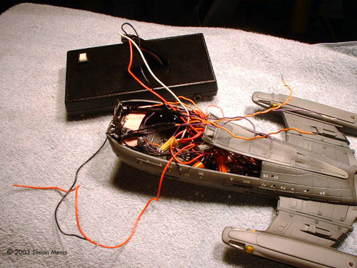
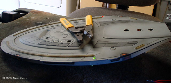
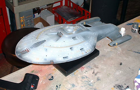
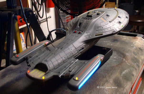
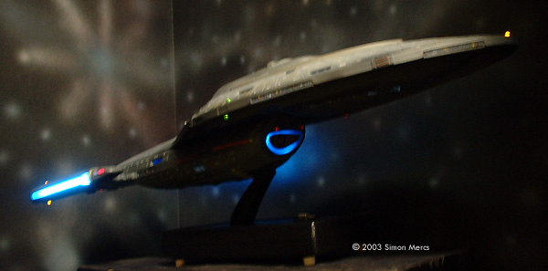
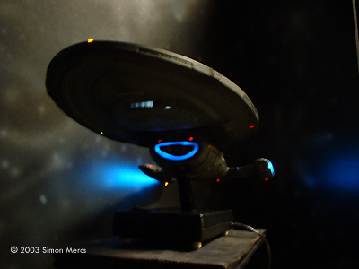
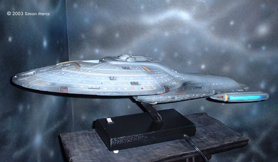
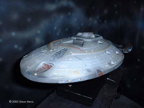
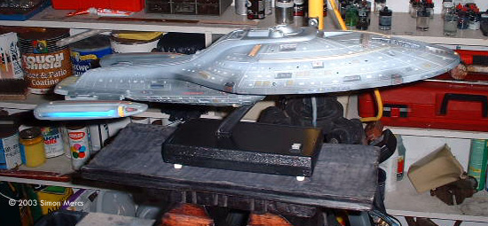
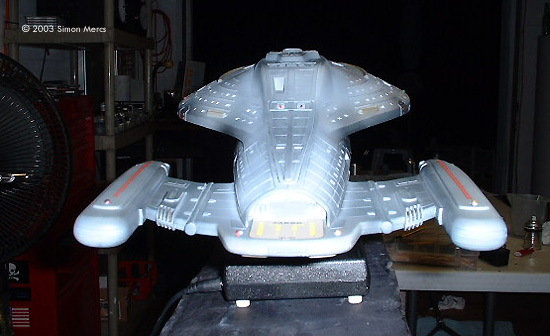
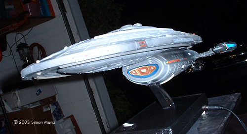
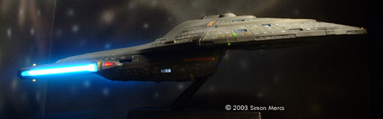
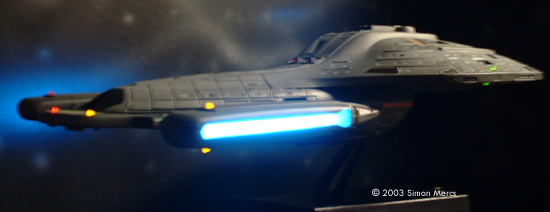
![[Click to enlarge]](sm_v/sm_voy297.JPG) ^ Saucer, assembled Image: These wires will connect to those in the engineering hull Image: Saucer light test Image: Hooking the model up Image: Wiring in the stand Image: One last part seals the model Image: Ready for decal work Image: Wiring outlet Image: Decal work begins Image: Saucer decals Image: Final light tests Image: Underneath the bow Image: Rear view Image: Beauty shot, starboard side Image: Port quarter Image: Port side Image: Saucer Image: Starboard side Image: Stern Image: Deflector Image: Right/ front view Image: Boldly Go |
Day 14 Well it's day 14 and final assembly of the saucer section with lighting onto the engineering hull is completed. All light tests are go. I made this a static stand connection, all bonded together. This keeps the wires hidden and also prevents damage to the tiny connections from too much movement and pulling. The decals were applied and sealed. I use the minimum of decals since I don't like too many over my paintwork. Clients can always apply more, to their taste, once they receive the prop. The prop is pretty much completed at this point. Other than a few touch ups and small details, I am finished with the Voyager. I think my client will be very pleased with the results, I certainly would be happy to get it as a Christmas present, all built and ready to go. Thanks for checking out my project! Regards, Simon Mercs |
![[List your model events on SSM]](http://www.starshipmodeler.com/resource/sm_events.gif ) |
| Visit our sponsors! | Advertise with us |
![]()
This page copyright © 2003 Starship Modeler™. Last updated on 24 December 2003.
![[Click to enlarge]](sm_v/sm_voy04.JPG)