
|
This ship, a Peregrin- class courier modified into a warship by the Maquis, was only seen (so far) in the pilot episode of ST:Voyager, one episode of TNG and two episodes of DS9. Monogram's kit is a decent offering - and with very little additional work, can be quite an eye-catcher, as Nigel demonstrates... Research | Design | Installation | Testing | Copyright Info |
![]()
|
By: Nigel Scott of Australia's SF Horizons |
|
![[Builder and Model]](maquis1.gif) Not sure I'd want to meet Nigel in a dark alley ... |
This is the record of how I added lights to the Maquis ship from Star Trek: Voyager (made by Revell-Monagram). It started out as one of those good ideas (at the time) and looked easy enough (at the time), but shortly after starting I realised that this was going to be a long one - especially armed only with a little knowledge of electronics and an article on how someone put lights in the Enterprise model kit. The actual building of the model is the same as the instructions. The lights used in the model were all lights and items that I could find around the house and at the local shops. After completing the model and seeing what else was available, I came up with different lighting ideas. However, this report will describe how I did it the first time. |
|
There are only a few steps to lighting a model whether it's straight from the box or a scratch built masterpiece. These are Research, Design, Installation and Testing. Research. The Maquis ship that appeared in the first episode of Star Trek: Voyager and was destroyed after a short life on screen. This made researching the location of the lights and the colours very easy (only one tape to look at) but during the episode not all the lights were visible. So to balance the design, if a light was found on the port side, it was duplicated on the starboard, etc, etc. The following is a list of the light location that I was able to find using video tape and magazine pictures:
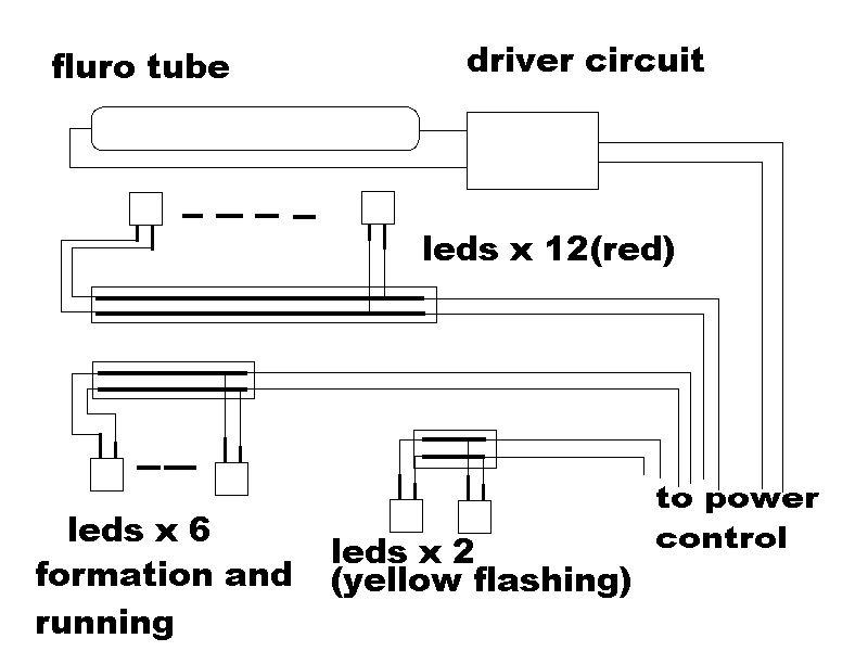
Design. The design of the circuit was very easy since I was using parts off the shelf. The main light, which was to light the warp engines and the cabin lights, started life as a two- in-one torch (flashlight bulb and flourescent tube in one unit- Ed.). When stripped down it consisted of the main tube, a globe, driver circuitry and case which makes modification very easy. As an added bonus, some of the case parts can be used as parts for other model kits and other projects. The next step of the design phase was the flashing lights. Some electronic catalogues have data sections in the back showing different circuits and components. In the back of one magazine there was a design for a multi-vibrator - basically only a 555 timer chip and a handful of other components wired together to make a circuit that switches on and off at any frequency you set it on. Some people may ask why not use a flashing LED instead: my reason is I just happen to have had a circuit built and lying around ready to be used. The next part was the formation lights. For these I decided to use LEDs and fiber-optic cable (taken from an old lamp) and to connect the different LEDs in parallel so that if one burns out the others will still work. LEDs were also used for the impluse engines. |
|
![[Finished Model on Base]](maquis2.gif) |
The stand was next. For this a piece of brass tube was used and all the wires were run down inside and out the bottom to a connector. The last piece to design was the base and this was going to be fun. The first base I had in mind was quite big and had a really cool spout and flashing lights, etc - but looking at the cost, size of the model, how much space was available and time, the base had to be reduced down in size to 600mm x 600mm. I wanted the base to look like a piece of the Bad Lands the Maquis ship flew into. To achieve this I had in mind some artificial spider web and translucent orange paint. |
|
Installation. Now the fun begins. The first thing that had to be done was the holes made for all the lights. For some it was easy - a simple drill hole through the plastic and a slight countersink on the outside. For others it was painstaking work, especially all the impulse engines and openings for the warp drive . The mid-ship and center grilles had to have gaps cut between the pipes to let the light shine through, and the plastic behind them had to be cut away. The next bit of cutting was for the impulse engines (red lights). This was fun (ha ha ha) because without a small cutting disk it is bloody time consuming to cut out the twelve square holes and then cutting clear plastic to match the holes. Once the clear plastic was cut, filed and glued into place inside the square holes, I cut some sticker material that lets light through and placed this over the clear plastic to diffuse the light (clear contact paper, also known as 'sticky-back' - Ed.). These stickers were then given two coats of Tamiya clear red paint for the impulse engines and clear blue for the warp engines. The panels at the back were glued into place (top of the model still off) and any gaps found were filled. All parts where light shines through were masked off and the inside surfaces of the model painted matte black, silver then gloss white to reflect as much light as possible. |
|
![[Interior Lights]](lights.gif) |
The next step in installing the lights is the mounting of the fluro tube. The mounting bracket used for the tube was made from the casing of the 2-in-1 torch. The casing itself was made up of a total of six parts, one of which is has a hole in it for the globe and its cover. This was taken out, cut to size and the hole made slightly larger to accommodate the tube. |
|
It was then glued into place (in line with the warp engine openings). The hole where the kit stand goes was enlarged to accommodate the brass tube (the stand). Then, three pieces of thick plastic were sandwiched together, two with a hole same size as the tube and one with a hole slightly smaller than the tube to act as a stopper. This assembly was glued over the hole for the stand to allow the wire to run down the tube. It also allows the stand to be removed for transport. Another three pieces of plastic were glued together and a hole drilled down the center (same size as brass tube) and the brass tube was glued into place. The next step was to add four smaller holes just in from each corner to allow mounting pins to lock the model onto the base for display but make it removable for transport. |
|
|
The LEDs were the easy parts to fix into position. Because CA glue (super glue) does not conduct electricity it can be used to glue LEDs into place without any special mounting requirements. I used the legs of the LEDs for the impulse engines as stands to get the LED in the right position to shine as much light as possible. A length of wire was soldered onto each leg of the LEDs (solid colour for positive and broken colour for negative) and the other end soldered onto a circuit board. |
![[LEDs]](rearlts.gif) |
![[Interior Lights]](maquis3.gif) |
All I can say is that if you want to light a model and think it is too much work just think about how great it will look in a dimly lit room... Think how amazed the other guys in the club will be when you power up, and all the lights come on (if you belong to a club; if not replace guys in the club with relatives). Lighting models can be as simple as putting a red LED into the eye of the Terminator or lighting R2-D2 from Star Wars. Some of my other projects include Horizon's T2 and AMT's snap-together B-Wing fighter. |
|
And remember 'The lights are with you .... Always'. |
|
![]()
Last updated 12 July 1999. This page Copyright 1997, The Lester Press. Article and images copyright 1997 by Nigel Scott. No portions of this page may be reproduced/reprinted witout express consent. ... so just don't do it.