
By Steven S. Pietrobon - images & text © 2004
I've been interested in space since childhood and my biggest wish was to get a model of the Airfix 1/144 Saturn V. My wish came true when I ordered the kit from BMW Models in England (who I still have £1.45 credit with) in 1976. I tried to get the Saturn IB the next year, but unfortunately it had been discontinued. All I could do was look at the large half page box cover in my 1973 Airfix catalogue. Fast forward 25 years, I found out through Ninfinger's Scale Models that Andromeda in Germany had bagged models of the Airfix kit. When I received the kit, there was no reference to Airfix, with an oval sticker on the bag proclaiming "Collectors Models Space Stop Saturn IB Includes 1:144 Lunar Module". I saw one of these kits on eBay, where the seller claimed that Collectors Models are from Japan. Unfortunately, this kit is no longer available from Andromeda. However, an unbranded copy for £29.95 is apparantly available from Magellan. |
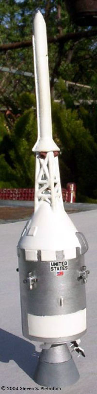
![[Big!]](sp_saturn1b.jpg) |
|
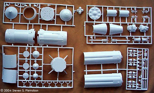
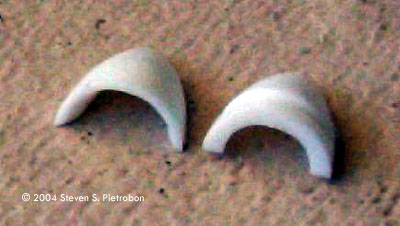
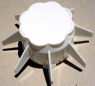
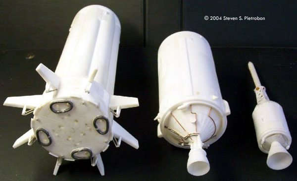
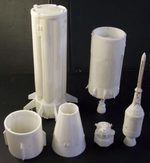
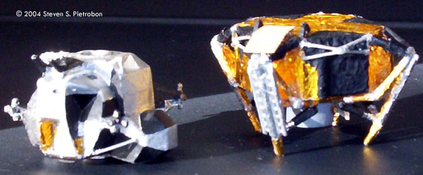
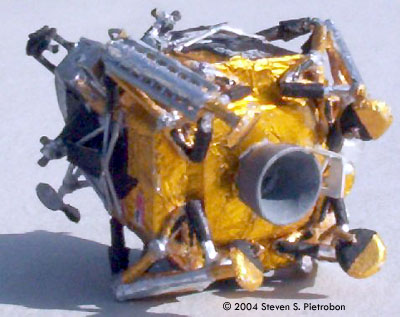
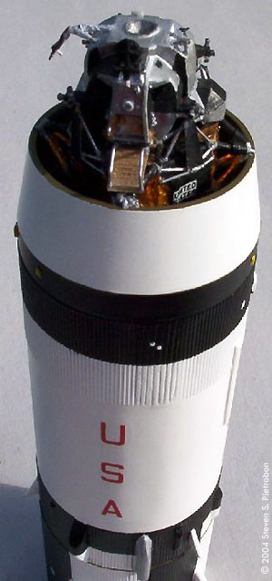
Image: Plastic parts Image: H-1 engine nozzles thinned out Image: Fins before filing Image: Stages before painting. The base of the S-IB shows the repositioned engine holes Image: Stages before painting. The new spiderbeam can be seen at the top of the S-IB. Image: Ascent and descent stages Image: Bottom of descent stage and behind ascent stage Image: Underneath LM-5 Image: SLA, ready to make history Image: CSM with LET Image: Scratch built stand Image: Masking of stages Image: With my battered Airfix 1/144 Saturn V from 1977 |
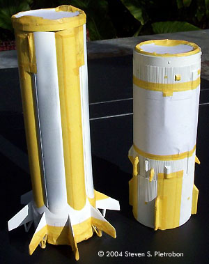
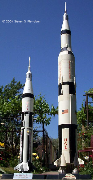
The Airfix kit was available from 1971 to 1976 and had a limited run in 1991, thus making it a fairly rare model. The S-IVB second stage, Lunar Module (LM), Spacecraft Launch Adapter (SLA), Command Service Module (CSM) and Launch Escape Tower (LET) are from the 1969 Saturn V kit. The CSM is a Block I version. However, Apollo 7 (SA-205) which this kit is meant to represent, used a Block II, which has a different radiator panel configuration than the Block I. The CSM is also about 4 mm too small in diameter, which is quite noticeable. The LM (which did not fly on Apollo 7) is an early version, having many of the same inaccuracies of the 1969 1/72 LM kit. Comparing against the 1/72 kit, it is less than half the size, being about 1/168 in scale. The S-IVB is a 500 version for the Saturn V, instead of the 200 version for the Saturn IB. The biggest differences are that there are three instead of two ullage motors and no side tanks for the two silver Auxillary Propulsion System (APS) Modules at the base of the stage for the S-IVB-200. The S-IB first stage and interstage are "new", but have the small fins and outer engine deflectors that were flown on only the first four flights of the Saturn IB. This makes this kit most suitable for AS-201 (SA-201) and AS-202 (SA-202) which flew unmanned Block I CSM's or AS-204 (SA-204) which flew LM-1 (instead of the ill-fated Apollo 1 crew in CSM-012). My kit looked liked it had been pulled from the mould a little early, with one half of the S-IB being a little flatter than it should be. The interstage halves were also slightly flat. Other than that, the kit was in very good condition, with no flash. The decals were also fairly good, although you could not see the stripes on the US flags, as you can on my Saturn V kit. Unfortunately, there is no stand included. The mould for this was either not purchased or lost after Airfix went bankrupt in 1981. First Stage I started by assembling the eight H-1 engines of the first stage. On the real S-IB, the inner and outer engines are different. The outer engines have the turbine generator exhaust exiting around the edge of the nozzle through a skirt. The inner engines turbine generator exhaust exits through the centre of the four inner engines. The kit parts though have eight identical engines. I decided to use the parts as is, although I thinned the exit nozzles using a small round file. The heatshield 13 of the S-IB had the four outer air deflectors sawn off (save these for later), the raised detail for the four outer engines removed, the four outer engines moved 2 mm outwards, the four inner engines moved 1 mm inward and the panel lines rescribed. I made new thicker outer engine heat shield skirts out of thick wire and superglued these in place. I wasn't happy with my first attempt and so I redid this. I used steel wire which was very hard to shape. Solder wire may have been much easier to use. Four small round exhausts between the outer engines were made from the nose probe of a 1/72 F-4E. I placed five bits of sprue into the S-IB base 26 so as to hold up the heatshield, as the four outer skirts had been removed. The leading edges of the eight fins were filed from their square edges into much sharper edges. Hatches between the fins were scribed. The S-IB fuel tanks 31,33 were glued togther with the ficticious fuel tank top 32 turned upside down. Plastic strip was liquid glued between the joins to strengthen the join, due to one of the halves being slightly flattend out. Position 1 and 3 of the S-IB are 180 degrees apart and are where there are two antennas side by side near the top of the stage. Looking from the base position 2 is 90 clockwise from position 1 and position 4 is 90 clockwise from position 3. These antennas were too far out, so I cut them off and glued them so that they were centered on their panels. The area around the antennas is flat, so I scribed the plates the antennas are on. The heatshield also has to be rotated so the inner engines are in positions 1, 2, 3, and 4. The holes between the large fins where the four small fins 27-30 would have been glued were filled in with putty, allowed to dry and sanded smooth. The corrugation between the fins is not correct, but I could not figure out a good way of correcting this. The eight hold down posts under the fins were made using plastic card and pins cut to the correct length. The pins should be parallel to each other (I initially had them going together). I cut the lips from each of the air deflectors. These were cut in half and glued to the base to represent the small new deflectors on SA-205. At the top of each LOX (liquid oxygen) tank to the left of the antennas I drilled a small hole (not all the way through the plastic) to replicate the vent holes. A small circle was scribed at the bottom of the fuel tanks to the right of the antennas for the fuel/drain hole. Thin plastic sheet 96.5 mm long and 2 mm wide was placed near the left edge of the fuel tanks in positions 1, 2 and 3 for cabling ducts. To replicate the top of the spider beam, a circle 40 mm in diameter of plastic card was used and scribed. My first attempt was too low on top of 32, so I had to rip it off, add short stands using sprue, and make a new spider beam to glue on top. The card was a little thin, and this caused bumps where the sprue stands were placed. Sanding down and rescribing fixed this. Interstage For the Interstage I removed the four tabs in each half as they can be seen on the inside. After glueing the halves togther, I glued a thin strip of plastic card along the inner join for added strength. The eight vent holes around the middle of the interstage were scratched out. The raised corrugation where the halves were joined were filed down and new corrugations were scribed. |
|
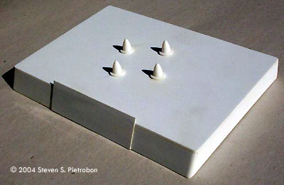
Second Stage I used this photo for the base of the S-IVB second stage. The kit part base 41 has raised detail going from the bottom to the top. I removed some of this detail and scribed extra lines and a circle around to be closer to the photo. Numerous bits of thin copper wire were added to replicate the piping seen. The large LH2 (liquid hydrogen) pipe was made using solder wire. I wrapped the copper wire with thin paper to replicate the white join in the photo. Notice that the LH2 pipe goes beneath 46, with the engine being in line. I removed the two side extensions at the bottom of 41 for the engine. I also shortened the middle extension before glueing on the J-2 motor. The inside of the motor was smoothed out to remove the join lugs. I also predrilled where the helium tanks would be installed after painting. This is at the base of the engine and on the opposite side, halfway up the base. The base of the halves has a flange which goes into the interstage. I sawed a lot of this off, but still left the hooks intact, so that the model can be taken apart. The top two flanges in each half were removed. The halves were glued together with a small amount of putty used to fill any gaps. The APS modules are in positions 1 and 3. The side lobes of these were sawn off. A new ullage motor was made using plastic card. The two holes for the ullage motor were filled in. One motor is placed on the opposite side of the main umbilical line. The other two are placed 120 degrees apart. The short umbilical to the left of the main umbilical had its left side sawn vertical. The umbilical was then filed down. Part 48 was not used and was replaced with a shorther length part I got from my spares bin. There are four raised squares on the top corrugation. The square to the right of position 4 was removed. The other three squares had the smaller raised squares filed down. Various small antennas were added to the top of the stage (which is the Instrument Unit). The raised corrugation along the join lines was filed down and rescribed. Lunar Module (LM) I measured the LM to be about 1/168 in scale. The slightly smaller scale was probably used so that the LM would fit in the narrower SLA. I had built one of these LM's in 1977 as part of my Saturn V kit. Airfix sent me a completed LM when I sent in a complaint slip for a leg that had gone missing. The tiny LM has only eight detail parts, the four legs and the four thruster pods. I also had built the LM following the instructions, which gives the basic black and white prototype scheme. This time, I wanted to build the LM to be like LM-5 "Eagle", the first crewed Lunar lander. I basically followed nearly all the instructions given in the November 1972 issue of Modelworld for the 1/72 Airfix LM and the September 1989 issue of FineScale Modeler for the 1/48 Monogram LM. Another excellent articlewhich I came across after I had completed the LM is the August 1979 issue of Scale Models for the Airfix 1/72 LM. I also used David Weeks' Monogram 1/48 LM who built a tremendous model as a reference source. Excellent photos of LM-5 on the Moon are in the Apollo Image Gallery. The ascent and descent stages are joined togther, so I sawed these apart, removing the excess plastic under the ascent stage. I made little cones out of paper for the docking probe at the top of the ascent stage and the top of the descent stage motor. I superglued these in place, before glueing the ascent and descent stage halves togther. The gaps in the top of the descent stage and botton of the ascent stage were filled in with plastic card. Any smaller gaps were filled in with putty. For the descent stage, I filed and sanded the antenna holder in quadrant 1 (forward left looking from inside LM), but I believe this should have been completely removed, as no large antenna was carried by LM-5. I made the helium tank bulge in quadrant 3 (right rear) circular in shape as per the instructions instead of the correct octagonal shape. After adding the gold foil, which makes a huge difference in appearance, I added a scratch built landing radar and heat shield under quadrant 2 (left rear). For the legs, I first sliced off the pads, so that I could glue them into the correct angle. I then started to wrap the legs with many tiny pieces of gold and silver foil. After doing this, I decided to make the legs more realistic, instead of the 2-D shape of the parts. The "butterfly" at the bottom of the legs were carefully sliced off. After wrapping in gold foil and painting the corners silver, these were glued under the descent module in quadrants 1 to 4. The short parallel beams were cut off and the two beams to the side of the main leg were bent inwards, so that the bottom of these two beams would be glued to the bottom of the descent stage. For the front leg, I had to slice these beams from under the ladder and make new beams from some metal pins. After the legs had been attached I made up eight short beams which attached to the inner points of the "butterfly" near the engine, joining up to the leg. After attaching the pads using superglue (which fogs the metal foil), I glued the left, right and rear landing sensing probes from under the pad to where the new beams came togther on the leg. The front leg does not have a probe. The porch was made from plastic sheet and scribed to give a corrugated finish. Ascent stage mounts behind the porch were scratch built and painted black. For the ascent stage I scratch built the renedezvous radar, S-band antenna, UHF antennas, docking target, EVA antenna (in the folded position), using tiny bits of plastic card, pins and supeglue. For the two large antennas I cut out tiny circular pieces of plastic card. These were placed in the dimple of a golf ball and the end of a paint brush pushed against them, in order to produce a dish shape. In launch position the rendezvous radar should be pointing backwards, with the S-band antenna pointing down. All the painting was done by hand, using mostly silver and matt black where appropriate. After the ascent and descent stages were glued togther, the scratch built exhaust defelectors (made from paper and foil) were attached, along with their copper wire beams painted silver. Copper wire handles were attached to the porch, and I even added the tiny hand hold on the ascent stage! I used the decals from the kit, putting the US flag in quadrant 4 (front right) and United States in quadrant 1. This was achieved by placing a rectangle piece of white decal first, following by the long United States decal cut in half. This is actually much larger than it should be. It would have been better to use a custom decal. I have to say that I am very pleased with the final result. I think the LM looks terrific! Spacecraft Launch Adapter (SLA) For the SLA I again removed the tabs from the halves, so that I would have a smooth inside. I decided to build this in the Apollo 11 version, as I would be using the RealSpace 1/144 Apollo conversion for Apollo 7. This involves adding two large hinges in four positions 90 degrees apart at the base of 61-62. I also added eight small bits of plastic card around all eight positions at the base of 61-62. The four separation lines were scribed. To fit the LM, I used a triangular file to make indentations for the legs at the top of 50. I also filed the insides of 61-62 to make sure that the legs and ascent stage would not interfere with the LM inside. Command Service Module (CSM) The first thing I decided is that I would glue the launch escape tower (LET) to the service module (SM). Previous experience with my Saturn V, shows that the LET falls off too easily, becoming quickly damaged. This meant that I did not use any of the command module (CM) parts 72-74 (which was way too small in scale anyway). I sanded off the Block I radiator panels on the SM and added the radiator panels for the Block II using plastic card. I followed the RealSpace conversion kit which was a mistake. The bottom large radiators should have a small thin radiator above them, and the top small radiators are the wrong size and in the wrong positions! Small semi circles were cut from thin plastic card and added to the sides for the antennas. I filled in the thruster pod holes and drilled new holes 45 degrees around. This is so that the thrusters line up correctly. At the base of the SM, I sawed the flanges down, similar to what I did for the S-IVB. I added a square shape rounded piece of thick plastic card, appropriately filed down and scribed. The engine bell 67 (which is very inaccurate) had the bottom two and top raised lines removed. I added the umbilical between the SM and CM using plastic card and putty. I scratch built the antenna at the base of the CM using the same techniques for the LM. This was quite delicate and came apart a few times while handling. Launch Escape Tower (LET) For the LET, I added two long pieces of thin copper wire at position 1 on the motor. Small holes were drilled in positions 1 and 3 for the LET jettison motors. Four exhausts were added at the top of the gridwork under the motor. The base of the motor has a ridge which was removed with a sharp knife and sanding. For the protective cover, I added the hatch at position 1 and various other bits using plastic card. In the grid work the bottom diagonal went from top left to bottom right. I cut these out and put them in bottom left to top right (not that anyone would notice!). I added eight short pieces or wire around and under the bottom of the grid. Where the grid attaches to the cover, I cut and filed these protusions down. Stand Unfortunately, the original stand is not included, so I decided to scratch build a copy of the original from my Saturn V. I used 1.5 mm thick sheet styrene. I measured the dimensions of the four sides and top and drew them on top of the sheet. I then scribed along the lines to give my saw something to guide on inititally. I sawed horizontal to the sheet which worked quite well. The five pieces were then glued togther, filled in with putty and sanded. The corners were filed to be rounded as in the original. The display sign at the front was made from 0.5 mm sheet styrene. After the engines had been installed onto the S-IB, the middle engines are canted out as they should be. This would make trying to use the engine holder 78 difficult, as the model would easily fall over. To solve this, I cut the holder into four pieces and glued them on the stand so that they would be underneath the four outer engines. This gives a very steady base. I placed the holders 22.5 degrees off so that two fins would be facing you, instead of one fin. I did this, as that is where I thought (based on photos) the CM hatch faced. The RealSpace instructions say that the hatch is in position 1, so I may be mistaken. Painting and Decals After all the stages were prepared, I sprayed everything with Humbrol 1 primer, followed by gloss white. The Interstage, S-IVB and SLA were joined together while I did this. I then masked up the S-IB and S-IVB using Tamiya masking tape and white paper. The base of the S-IB should be painted starting from position 1, B/B, B/W, W/B, and W/W where for example B/W means black over white. This is the same paint scheme used at the top of the S-II on the Saturn V. The S-IB was then placed in a paper bag, leaving only the spider beam exposed. The Interstage, S-IVB and SLA were similarly masked with paper and tape to leave the insides exposed. I had a lot of trouble finding the right colours to choose. For the bottom and top of the S-IVB I used Humbrol 148 Radome Tan. I don't think this is the correct colour, but it was the closest I could find. For the insides of the SLA and spiderbeam, the Apollo Image Gallery provided excellent colour photos. The colour is probably some zinc chromate, but I could not find a match. So, I mixed up some Humbrol 113 Matt Rust and Humbrol 117 US Light Green until I got the greeny brown shade I was looking for. This was sprayed on the spiderbeam, inside the interstage and SLA, and the inside walls at the top of the S-IVB, after the dome had been masked. I painted the edges at the bottom of the S-IVB by brush. After the paint had dried, the masking was removed, touch ups performed and the antennas painted yellow. The APS modules were painted silver. After spraying the CSM and LET with satin clear, the radiators and protective cover were masked. The SM was then painted silver. The top half of the engine was painted aluminium and the bottom half grey. The inside of the engine was painted silver. Note that Apollo 7 had white areas around the thruster pods which I intend to add for the RealSpace kit. After the decals had been applied to the S-IB and S-IVB, the stages were air brushed with satin clear. For the S-IB, Airfix only provided four of the eight position markers. A set of four markers in opposite colours is needed for the other side of the fins. The Airfix markers goes onto the white sides and the opposite markers goes onto the black sides. I printed a new set of all eight markers on white decal paper. You can download these markers here. The final details were added to the spiderbeam using some scratch built parts. The outer engine skirts of the S-IB were painted silver. The tops of the H-1 engines were painted aluminium and the bottoms silver. The insides of the engines were painted steel. These were then glued in place. A stand for the heat shield between the four inner engines was also made. The S-IVB engine was painted with Revell silver on the outside and aluminium on the inside. Helium tanks were made from pearls from a broken necklace. These had a hole drilled through. One end was sealed with putty, while the other end had a small pin superglued in place. After painting satin white the tanks were superglued to the engine and base of the S-IVB. The stand was sprayed with several cotes of Tamiya satin black, but it came out a bit splotchy. So, I sprayed some Humbrol satin cote on top to give a more even finish. The last thing to do was put the stand decal on. This is too large, so I cut off "Apollo 7" from the top of the decal. Conclusions This had been by far the longest and most difficult model I have constructed. A great deal of work was put in accurising and detailing the model. I also had to learn a few tricks, like scribing and using metal foil. While building the model though, I could not help but let a out a few "Holy smokes!" as various stages were completed. The LM and Saturn-IB are indeed beautiful to look at. Like any model, a bid of elbow grease can make a great model out of just about any kit. This one though requires a bit more than normal! Its not that the kit is badly constructed, its that it is so inaccurate and lacking in detail. It is hard for me to recommend this kit to anyone, but what other choice do you have for a 1/144 kit? The RealSpace 1/144 Saturn IB is US$100! Plus you don't get a lunar module and there are missing details like the S-IB holddown posts. The CM radiators are not accurate, the SLA has crooked hinges, and the LET motor is oval shaped since it was copied from the Airfix kit. Working with resin also has its difficulties. I built this kit for personal reasons as I wanted one so badly when I was a kid. I went the full hog which has resulted in a great looking model. I have also learnt a lot about the Saturn IB. I read somewhere on the net that someone has spent 15 years building this kit and has still not finished, so I'm not doing too bad! Good luck to all of you who attempt this kit. |
![]()
This page copyright © 2004 Starship Modeler™. First posted on 4 November 2004.
![[Click to elnarge]](sp_saturn1b_bag.jpg)
![[Click to elnarge]](sp_saturn1b_base.jpg)
![[Click to elnarge]](sp_saturn1b_stage1.jpg)
![[Click to elnarge]](sp_saturn1b_lm3.jpg)
![[Click to elnarge]](sp_saturn1b_top.jpg)
![[Click to elnarge]](sp_saturn1b_bottom.jpg)