
|
By Evan Jones - images & text © 2006
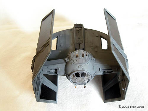
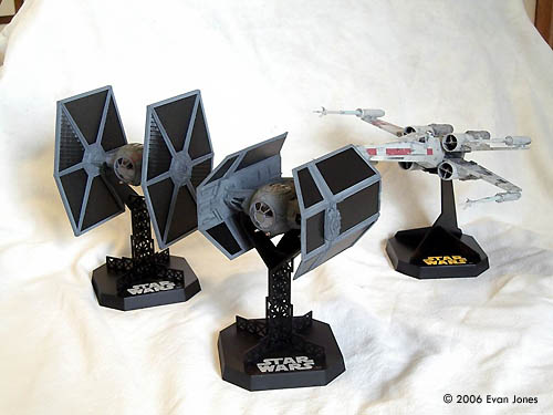
I always wanted to have all the fighter spaceships used in the final battle sequence in the first Star Wars movie Episode IV: A New Hope. Fine Molds produced excellent X-Wing and TIE Fighter kits. However, the only version of Darth Vader's TIE Advanced X1 was the old MPC kit, (since re-issued a number of times) which was in either 1/36 scale, or 1/51 scale, depending on the source. I used the Fine Molds TIE Interceptor kit as the basis for the Advanced X1 and used the MPC kit as a template and guide for making the modifications. I started by assuming that the MPC kit was twice as large as the Fine Molds kits, based on measuring the diameter of the round front cockpit window. |
![[Please click to enlarge]](ej_vader_01_TIEX1Front17sml.jpg) |
|
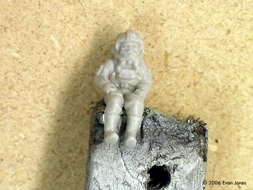
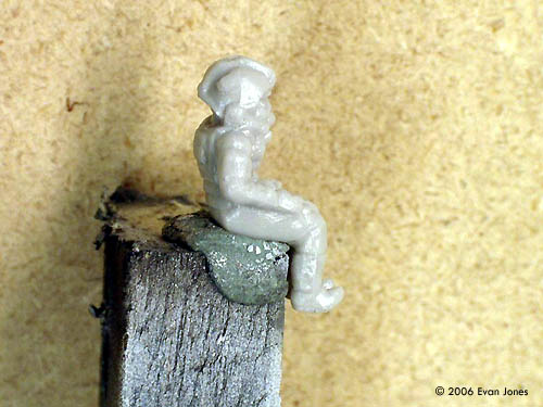
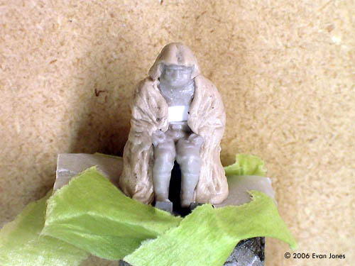
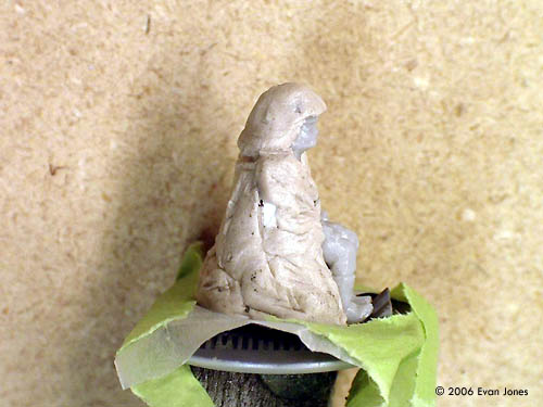
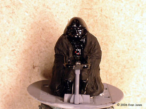
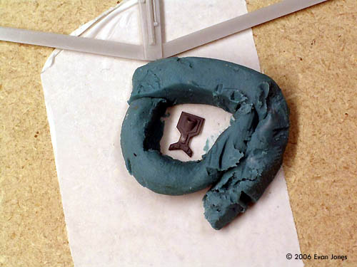
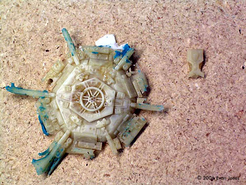
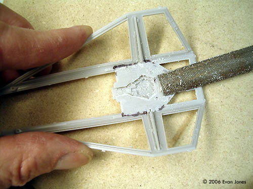
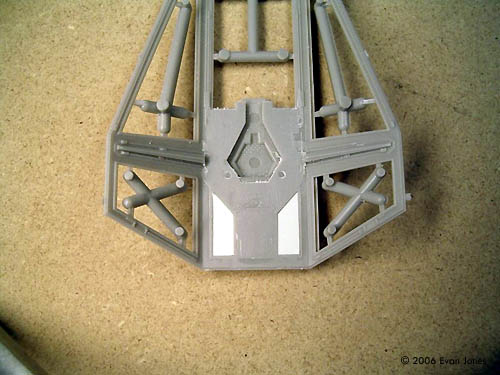
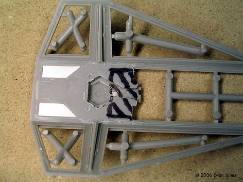
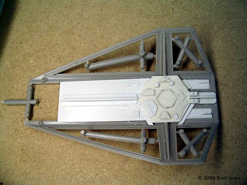
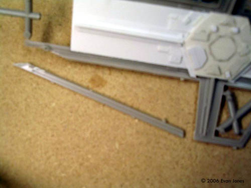
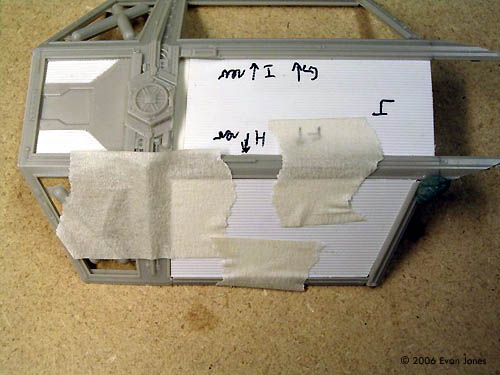
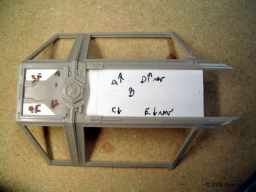
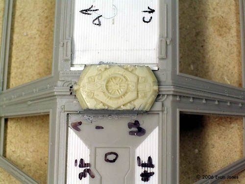
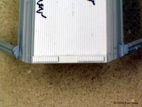
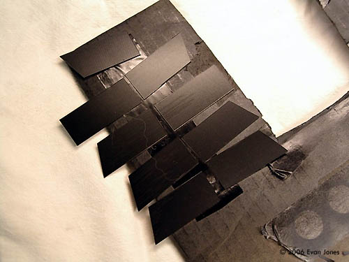
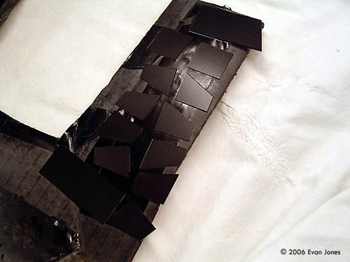
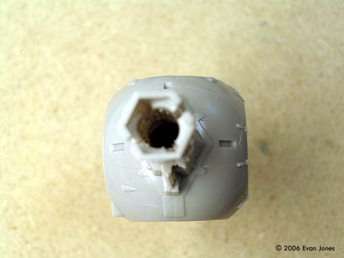
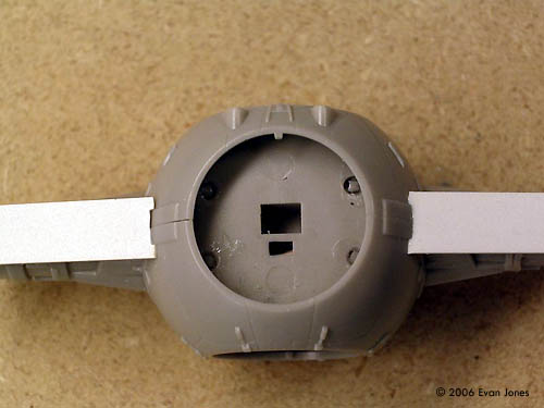
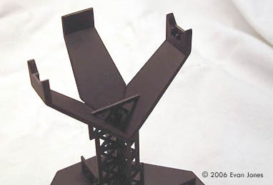
Step by Step Photos: Image: Pilot before conversion. Image: Side view Image: Darth Vader before painting Image: Note the white styrene insert and the Quikwood material built up for his helmet and cape. Image: Painted Image: Another look Image: Parts being cast. Image: Results Image: Another look Image: After filing smooth, holes were filled with sheet styrene Image: Then shaded area was removed Image: Details of inner wings were built up with sheet and strip styrene. Image: Another look Image: One section of frame was removed and a solar panel cut to desired shape and size Image: Then the frame was cut to match the panel. Image: Panels were taped place while superglue sets on frame pieces. Image: Each panel was labelled so that it can be fitted to the correct location later on. Image: Outer details were filed off and then resin cast piece glued on. Image: Another look Image: The outer rear part of wing were detailed with sheet styrene and some small pieces of the solar panel V-groove sheet. Image: The inside of the wings could probably use more finer detailing. Image: Solar panels were mounted to double sided tape on cardboard. Image: Pieces were painted with Tamiya Semi-Gloss black straight from the can. This gives a shinier finish than using thinned bottle paint. Image: ... then rotated 30° and glued back on. Image: Strip styrene 0.5 mm (0.020") was added to top and bottom of arms. Image: Notches were cut in bottom pieces and edges were bevelled for a tight fit. Image: Back of arms were cut from 0.5 mm (0.020") sheet styrene, with indent made from square tube, cut lengthwise. Image: Edges of styrene beveled to make joints tighter and use less putty. Image: Rear Inserts were detailed with styrene rod, 1.0 mm (0.040") and 0.5 mm (0.025") diameter. Image: Front arms were made of 0.5mm (0.020") sheet styrene. They were taped temporarily in place and the front joint only was glued. Image: When dry, it was removed and the opening for indent was cut out. Image: Front of arms with openings cut out and markings for scribing panels. Image: The indent was made from square styrene tube, cut in half at an angle, split open and widened and then the edges bevelled to fit inside arms. Image: In order to make the front arms fit, a lot of the existing arm was removed using a Dremel tool. Image: The indent was detailed with styrene rods and sheet, wire and a small pieces cut from parts G4 and G5. Image: More detail Image: An internal brace for the body was cut from 3.2 mm (0.125”) thick sheet styrene. Image: This picture shows what it looks like once glued in place. Image: More layout Image: The brace was glued and clamped onto one body panel and left to dry overnight. Note that brace forms front end of the larger hole. Image: The other half was glued, clamped and left to dry overnight. Image: Central spine of body was made up of sheet styrene, cut to shape and glued in place. Image: Bottom detail were made of: sheet styrene with drafting tape straps, sheet styrene with slots cut in, sheet styrene, styrene rod. Image: Slots were laid out using #66 drill to start. Image: Slots Image: Top of body was detailed with sheet styrene, styrene rod, wire, styrene half round, sheet styrene with slots cut in and some details cut from part G2. Image: The end was detailed with pieces cut from parts G2, G4 and G5. Image: The detail part for the larger opening was made from styrene rod and tube. Small raised panels on the body and arms were made from 0.25 mm (0.010”) and 0.50 mm (0.020”) thick styrene. Image: The rear just before painting. Tamiya putty was used on the joints. Image: Looking good Image: The stand modified to hold model – the original arms were changed at the top to a different profile and a third arm from TIE Fighter kit was cut down and added to the rear to hold up the back of the model. Image: Another look Image: After airbrushing stand with thinned Tamiya Semi-Gloss Black (taken from bottle), the area around the lettering was masked. The paint was sanded off the lettering and then finer sanding pads (from 3200 to 12000 grit) were used to highlight the Star Wars logo and give it a shinier finish. |
However, as I got into the build I discovered that the scale differences were not the same:
The Wings/Solar Panels There are three main options to doing the wings/solar panels:
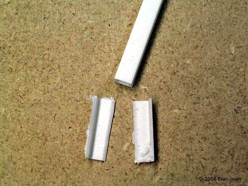
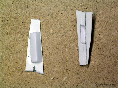
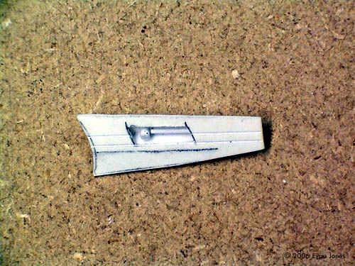
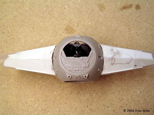
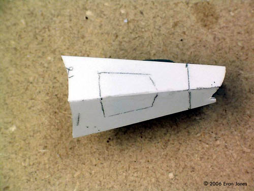
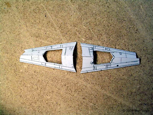
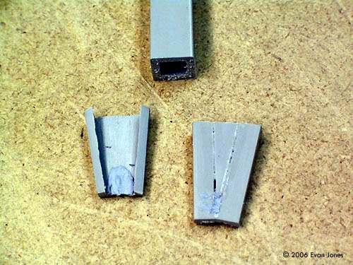
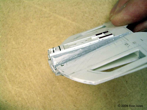
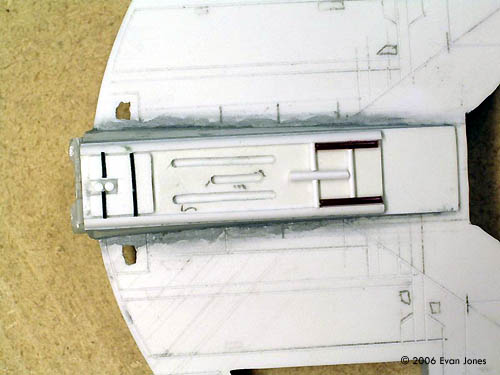
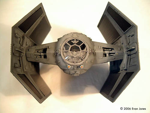
By turning the wings of the TIE Interceptor backwards, the front portion of the wings was pretty well done. The pattern of the solar panels is different than the TIE Fighter and is a raised, rectangular pattern. I thought that I would initially make castings of the existing solar panel inserts and splice them together to make the larger panels of the X1. However, this looked to be very time consuming and difficult to replicate accurately. In the end, I replaced all the solar panels with Evergreen V-Groove sheet styrene (number 2025, 0.64 mm (0.025”) spacing 0.5 mm (0.020”)). This gave some texture to the panel, although not perfectly accurate. The kit panels were used as templates for making V-Groove replacements. Care was needed because not all the panels were exactly the same – some edges needed to be beveled to fit correctly into the frame. The longer top and bottom frames of the Interceptor wings were cut off. These were then cut and filed to make the longer back portion of the wing. There was just enough of the frame to complete the top and bottom of the wing. Styrene strips were used to build a frame for the center part of the wing. Using the MPC kit as a reference, various styrene sheets, strips and rods were used to add the detail to the inner part of the wings. The outer part of the X1 wings have a circular shape that is not quite the same as on the TIE Interceptor. A mold was made of the shape from the TIE Fighter and two pieces were cast from resin. These pieces were then cut to shape and added to the wing, with some putty used at the joints. The Pod Arms The arms connecting the pod to the wings are bulkier than the TIE Fighter/Interceptor kits. The arms were also at a different orientation with respect to the cockpit - flat on top and bottom, whereas the TIE Fighter/Interceptor arms were pointed. In addition, there were some mechanical details sunk into the arms that needed to be replicated. The conversion started by assembling the TIE Interceptor cockpit. This meant that the interior had to be built up first (see below under Darth Vader figure). The arms were cut off with a razor saw, turned 30° and glued back on. Sheet styrene strip 0.5 mm x 6.4 mm (0.020” x 0.25”) was first added to the upper and lower arms. Sheet styrene 0.5 mm (0.020”) thick was used to make the other sections of the arms. Openings were made for the inset details for both the front and back of the arms. Styrene shapes at 90° were cut and placed behind the rear openings. These were glued on and detailed with styrene rods of various thicknesses. The larger front openings were made from cutting square styrene tube, splicing in a triangular piece and adding to the arms. In order to minimize the use of putty, all the pieces were cut precisely and bevelled on certain edges to make the joints and gap free as possible. Panel lines were scribed to match the lines on the larger MPC kit, although they were simplified somewhat. I learned the hard way that the panels should be scribed before being glued on. The Body The X1 has an elongated body section on the back. There are two distinct sections to this
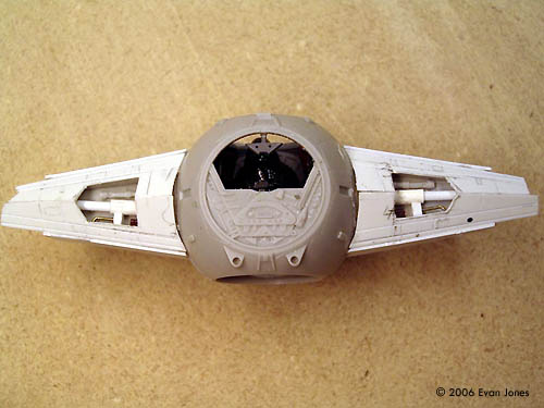
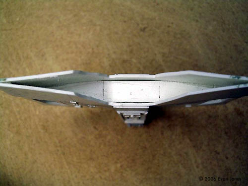
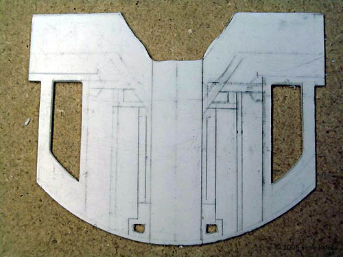
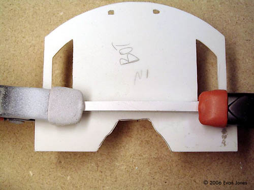
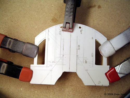
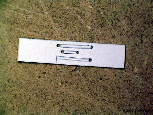
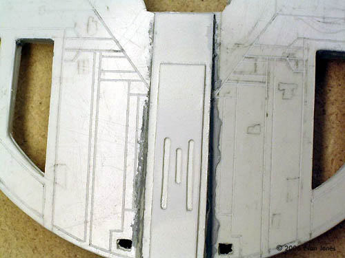
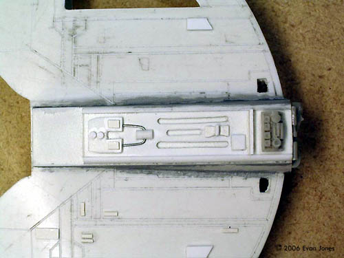
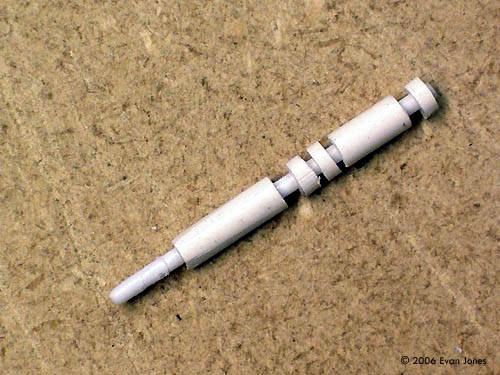
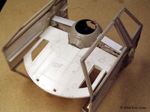
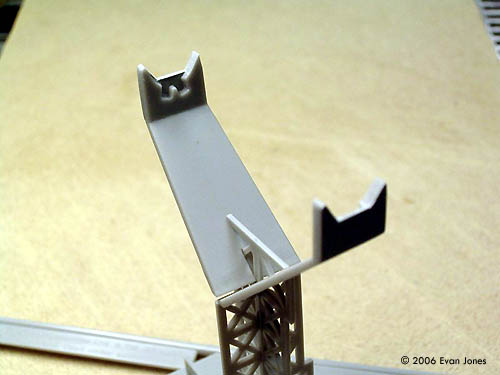
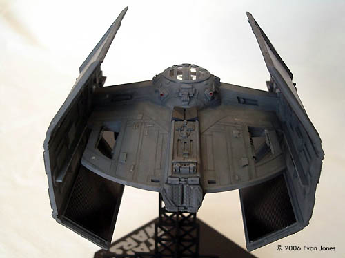
The longer, rear section of the body was built using sheet 0.5 mm (0.020”) sheet styrene and the MPC kit as a guide. Two copies were laid out for the bottom and the top, with the four holes and panels drawn on the sheet styrene. Since the rear section was not the same thickness across the width or length, an inner bulkhead was cut out of 3.2 mm (0.125”) sheet styrene. After scribing the panel lines, the upper and lower sheets were glued to the bulkhead in the interior and to each other on the outer edge. The front part of the section was shaped to fit the back of the pod and the new, thicker arms. The thicker center section was built using 0.5 mm (0.020”) sheet styrene for the sides and top. Another piece of 0.8 mm (0.030”) sheet styrene had the slots cut in them using a #66 drill for the ends and a sharp #11 blade and straight edge for the joining the holes together. Small pieces of styrene strip, rod and sheet were added for the various mechanical details on the body to match the MPC model. The MPC kit shows that there are four ion engines on the back of the cockpit, compared to two on the TIE Fighter/Interceptor. I made a mold of one of the engines and cast some extra pieces for these details. Dark Pilot Although difficult to see inside the cockpit, I decided to have some fun and convert the pilot figure to look like Darth Vader. It started by slicing the figure in half horizontally just above the arms. This location meant that I did not have to worry about changing the height of the controls. A section of 2 mm (0.080”) square styrene rod was glued between the two parts. This gave the figure the correct height for Darth Vader. The bumps on the helmet and the hoses on the face mask were cut off using a hobby knife. The figure was glued to the seat, excluding parts A2 (seat back) or A11 (arms) as this would be covered by the new figure. Using the MPC figure for guidance, I then mixed up a two part epoxy used for fixing holes in wood. It is made by Polymeric Systems (www.polymericsystems.com) and can be found at various hardware stores (I got mine from Lee Valley Tools in Canada). This product is easy to work with, can be worked for about 20 minutes and can be sanded, drilled and painted after it sets. This epoxy was draped around the body and some folds and wrinkles sculpted using a little spatula. The helmet was done the same way. Once dried, the helmet was sanded smooth. A tiny triangular piece of .25 mm (0.010”) styrene sheet was cut out and glued to the face to serve as the Darth Vader mask. The helmet, gloves, chest and boots were brush painted with Tamiya X-1 Gloss Black, while the rest of the body and cape were Tamiya XF-1 Flat Black. Silver and red paint was applied with a sharpened toothpick to the triangular face mask and the chest piece to simulate some of the buttons and details of Darth Vader’s suit. The TIE Interceptor stand would not hold the new model because of the rear extension. The arms of the stand were modified to match the profile of the new arms. A third arm (from a TIE Fighter kit) was modified and glued in place to hold the rear section. Painting The solar panels were painted Tamiya semi-gloss black directly from the can, which gives a finish with much more gloss than using the thinned bottle paint through an airbrush. The rest of the model was Tamiya XF-66 light gray using my airbrush. Some smaller details were brush painted. An excellent masking kit from Starship Modeller was used to mask off the cockpit front canopy window and the top of the cockpit. Finishing Touches Left over decals from both the TIE Fighter and TIE Interceptor were placed on different spots on the model. The technique used was the following:
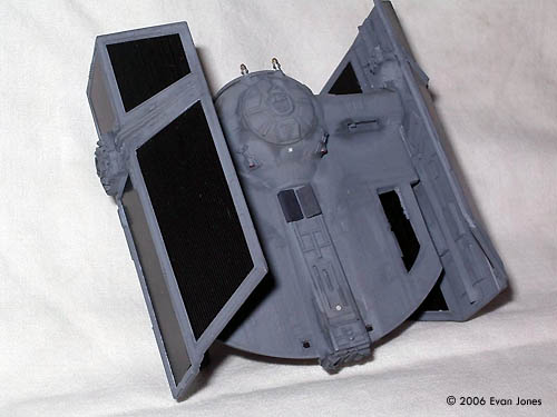
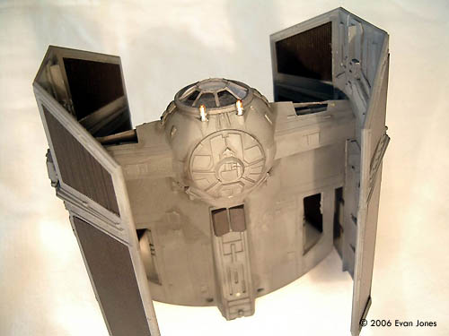
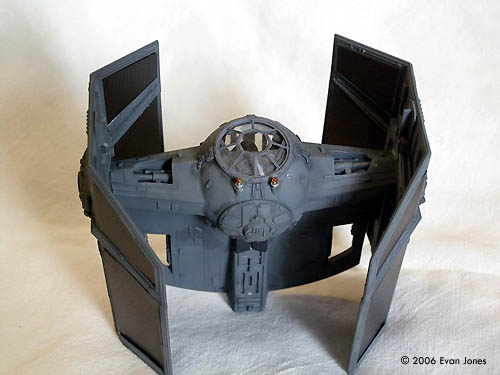
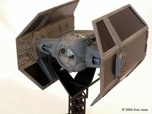
A light enamel black wash was added to the entire model to bring out the detail. The guns on the front were brush painted silver, then Tamiya clear orange on the front part. A little spot of Tamiya X-7 Red was put into the exhaust ports of the ion engines. The stand was painted Tamiya semi-gloss black from the bottle, thinned and shot through an airbrush. This gives a really nice finish that is shinier than flat black but not quite semi-gloss. Completed Model: Image: Underneath Image: Another look Image: Front view, low Image: Above/front Image: front/right Image: Front view Image: Rear view Image: All three ANH fighters Image: Again |
![]()
This page copyright © 2006 Starship Modeler™. First posted on 1 March 2006.
![[Please click to enlarge]](ej_vader_TIEX1Front20xsml.jpg)
![[Please click to enlarge]](ej_vader_Darth08.jpg)
![[Please click to enlarge]](ej_vader_Casting01.jpg)
![[Please click to enlarge]](ej_vader_Wing01.jpg)
![[Please click to enlarge]](ej_vader_Arms01.jpg)
![[Please click to enlarge]](ej_vader_Body02.jpg)
![[Please click to enlarge]](ej_vader_Mockup01x.jpg)
![[Please click to enlarge]](ej_vader_Assembly.jpg)
![[Please click to enlarge]](ej_vader_TIEX1Rear04sml.jpg)
![[Please click to enlarge]](ej_vader_TIEX1Top03xsml.jpg)