
|
By Mark Yungblut - images & text © 2002 Scratch building or "model making" is an art that is a logical progression from the advanced modeling techniques used in building kits out-of-the-box or kit bashing. These techniques and a few others are all that is necessary to start scratchbuilding. In addition to the techniques, there are a few qualities that one must strive to master. These qualities aid in creating a well-executed scratch built model. The first quality is patience. An accomplished scratch builder has plenty of this to spare, and knows when it is time to set the project they are working on aside for a while. This is very important, as it is very easy to get too absorbed in the moment and miss some of the little things that can create flaws in a model - or worse, lose perspective of the overall project. |
![[Click to enlarge]](my_scratch/aPicture30.jpg) |
|
Second, do not fear failure. Even the most experienced scratch builders fail to make things "come together" now and then. If a part being made or an element of the overall design does not work, then consider it a learning experience and try again. This is key to building a stable of reliable techniques.
Finally, you need the willingness to "take a leap of faith". Experiment with new techniques and/ or create a new one. Sometimes that's needed in order to meet the desired goal in a project. Some would call this "bravery", and that is an apt description. If it doesn't work, then refer to quality number two. The aforementioned qualities are not all that is necessary, and there are other qualities that help. These three, however, will give anyone a good start down the path of scratchbuilding. Well, enough pontificating. Time to get on to the building. Planning the Project |
|
|
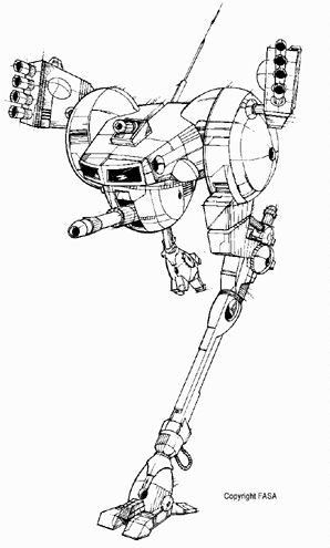
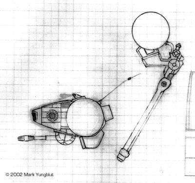
Image: This is the redesigned Locust by FASA. Image: This is the sum total of the drawings used to build this project. |
For the purposes of this article, I have chosen a Battletech Mech as a subject. The mech is called the Locust, and and was one of the designs used by FASA in the first addition of the tabletop combat game. The origin of this design was a Japanese anime titled "Crusher Joe". In that anime, the mech was actually a robot called an "Ostall" and was not as "beefy" as the designers at FASA recreated it.
FASA redesigned the robot to be a "light mech" battlemech. This meant that it was fast, lightly armored and primarily used for recon missions. In the early 1980's, a Japanese company called Nitto made a model of the "Ostall" as depicted in the anime. I decided to rebuild this mech depicting the "beefier" version from FASA. I began this project by doing a set of "sketches". I did not bother to create a full-fledged set of plans showing all the views, as this is not required for the techniques I used to make this model. All that I needed was detailed side view and a top drawings, to scale. These were done using a very fine (.03mm) mechanical pencil and a ruler, on graph paper laid out in 1mm squares. Once the initial drawing was done, I made 15 or so xerox copies to be used in the building process. Just a side note here: I prefer to work using a metric scale, as it seriously eases the math needed to lay out the parts in sheet form. |
|
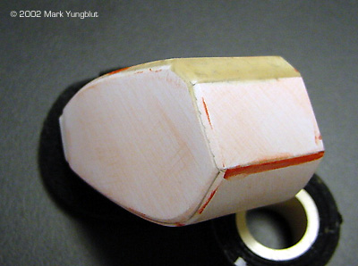
And So It Begins�� I started this model by building the main fuselage or body of the Mech. The parts for this were started, by very lightly spraying the back of some of the copies of the plans with spraymount. They were then adhered to some .03 styrene sheet. This included the top, the angles section for the top rear, the bottom and the two sides. Once these parts were cut out and the edges filed square I was read to "form" these parts to the desired curves. As noted in the plans, the sides curve inward towards the nose and the top curves down slightly in the same direction. The bottom curves slightly to the nose and severely curves around the back, bottom up to the back. These curves were accomplished by taking the individual parts and running the respective inside surfaces over the sharp edged of a table while applying pressure. This resulted in the gentle curves require for the top and the sides. Running the bottom part over the table edge multiple times until it held a curve similar to that which was desired created the severe curvature of the bottom section. This technique is similar to the one used to curl ribbon when making a bow. |
|
|
Once the parts were properly shaped, they were glued together, using square stock as extra support in the corners (which was also curved to match the shaped of the sides). It is important to note that the square stock was set back from the edge by the thickness of the sheet styrene to aid in creating a flush seam. The additional interior bracing also came in handy when the edges of the body were beveled, as the angle and width of the bevel was greater than the thickness of the .03 sheet styrene. After the body was glued together, the "angled" section of the nose was begun. This had to be done as a two-step process, as the "outer shell" had to hang over the window area by 3mm. Measuring the finished dimensions and then subtracting the thickness of the .03 styrene determined the overall dimensions of this part. |
|
|
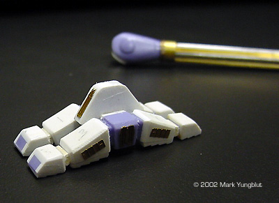
The next step was to create two disks that would end up being the base plates for the shoulder actuators. These two parts needed to be mounted to the body is such a way as to remain parallel to one another and the centerline of the body. Additionally, they both needed to be mounted so that they were 4 mm above the top of the body. Using a compass, I scribed two disks in .03 styrene and popped them out. I then stuck them together with some double-faced tape so that they could be shaped and the edges filed square at the same time. Once the parts were shaped, they were glued in place on the body. I shimmed the front and rear edges of the disks so that they would stick out from the sides and remain parallel. After drying, I filled the remaining gap with epoxy putty and smoothed it to blend the area with the body. To smooth the putty, I use a very small soft, flat brush and alcohol. The same technique was used to create the platform for the gun turret under the "chin" of the mech. |
|
|
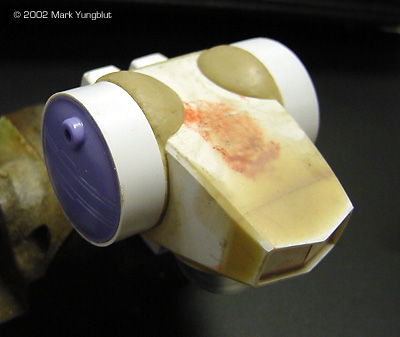
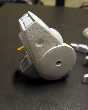
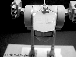
Image: This photo shows the main body from the rear. Note that the small angled section where the top meets the back has been covered with epoxy putty and reshaped. This was done because one side of the angled section ended up drying in place at a lower angle relative to the plane of the top than the other. The putty was used to compensate for this defect. Image: Here we see that the "half domes" have been roughed in to finished off the hips. This was done in epoxy putty and smoothed with a �" soft, flat brush. Once it had set, I needed a total of 20 minutes to finish out by wet sanding. These views show the housings for the visible heat sinks in place on the master. Image: From the front |
I then began "fleshing out" the main body of the mech. I started by laying out cover fors the "nose". Once these parts were cut out, finish sanded and glued in place, I noticed something that had happened since the construction of the main body. I ran a straight edge over the top plain of the body and noticed that it had sunk in the middle. I did the same for the sides and noticed that to a lesser degree that it happened to the sides forward of the "hip" plates. This fault was corrected with epoxy putty smoothed and then wet-sanded with 400 grit sand paper. This was done at the same time that the "hip" was filled out by building the semi-dome blended to the body using epoxy putty.
One of the most important mechanical devices on a Battletech mechs is a heat sink. These devices are critical to dissipating heat generated by the fusion engines and energy weapons. These parts were the next thing needed to be added to the master. To follow the plans, I needed to add the three visible heat sinks to the master. The three needed to be built as one larger heat sink on the bottom and two on the rear. This is another example of where I saved time by using existing parts to make the grill faces. The housings for the heat sinks were built up from styrene. With the bulk of the work on the main fuselage completed, it was time to start on the upper and lower legs. In order to complete this task, I chose a different method to see to its competition. I call this method "laminated parts". Some may ask: "Why go to the trouble?" but to this I say the end justify the means. In order to create a set of legs that will support the overall weight of the model, and not warp from that weigh, I had to use mixed media. The main shaft of the leg is made from square aluminum stock, which needed to be joined to styrene upper leg. |
|
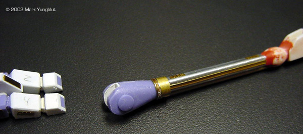
To build the upper leg/ knee joint, I sandwiched four layers of .03 styrene together using double-sided tape. I then took two copies of the plans and tacked them to the styrene. Once that was done, I cut the parts out with a jeweler's saw and peeled the layers apart. Because the middle layers of the four were the same thickness as the square stock, I was able to cut out a rectangular shape form the "football" shape at the end of the styrene that adjoins the aluminum stock. Additionally, I cut the "socket" for the knee joint out of the middle two pieces of styrene. The four layers were then glued together, and the aluminum stock was glued in the socket with 5-minute epoxy.
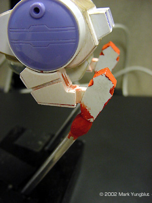
Once both legs were roughed out, I started the finished shaping and filling of the knee joint and the shoulder areas. I built the shoulders of the Locust using two existing semi-domes and wrapping several layers strip styrene around a piece of metal tubing to make the tube flush with the edge of the semi-dome. The lower sections of the shoulders were built using the same laminating technique as with the knee joint. The lower portions of the legs were detailed with etched brass strips and a piece of brass wire. The ankle joint was created using several pieces of brass tubing and two existing pieces out of the scrap bin. The feet were built using smooth sheet styrene and sections cut from a "corrugated" sheet from Evergreen plastics. The corrugated pieces where used to simulate a tread pattern on the bottom of the "toes". All the seams were filled and the edges beveled as per the original art from FASA. |
Image: This shows the "football" shape that the square stock was inserted into. Image: The feet and lower leg Image: The feet roughed in, with detail plates added. Image: Nearly complete Image: The lower leg, with all the etched brass detail added Image: Underneath |
|
Finishing the Build |
|
|
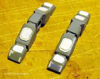
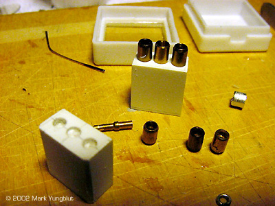
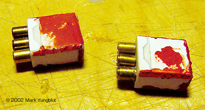
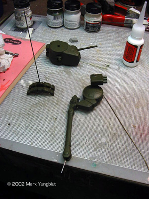
Image: Here we see the scribing done to one of the sides of the main body These shots show the building of the missile launchers. Image: Roughing out the box by wet sanding Image: Launcher tubes were cut from brass tubing Image: The nearly complete assemblies |
With the basic construction completed, it was time to start with the little details and finish filling the seams that had not been fixed. I built the main gun out of brass tubing, and the tip came from Bic lighter. The dome for the "chin" was made from a Plastruct clear dome. And a slot was cut to accommodate the gun tube. At this point, the entire model was undercoated with Krylon light gray sandable primer. This allowed me to see if there were any seams or flaws that had not been caught in the second pass. I also began to scribe the limited amount of seam lines that were needed on the main body. The other thing that I did at this time was to start adding some if the thin plating that was needed to the roof of the main body, and on the feet.
The next detail was to build the two missile launchers that go on each shoulder. I built the main bodies of the missile launchers from two pieces of thick styrene that were glued together with Tenex glue. When the glue was dry, I cut the rectangular shapes to size, and wet-sanded the six surfaces on a board to which I attached a piece of 400-grit sandpaper. I then laminated thinner sheet (.02) to the outside of the block and included the gap that is shown on the outside surface of the launcher. I also marked off the end that needed to be drilled for the missile tubes and drilled them to the proper diameter to accept the tubes. The actual tubes where made from more parts from the inside of a disposable lighter. After the holes were drilled, I beveled the edges of the missile launcher and gave it a final putty job to fill the remaining seam. |
|
The mounting brackets for the shoulders were made from rectangular brass tubing. And one end was beveled and curved to fit the contour of the semi-domes on the shoulders. Once the brackets were cemented into place (using 5 minute epoxy) and cured, I mounted the shoulder piece in a vise and sanded the outside surface of the bracket to a proper angle. The angle needed to be such that the missile launcher would seat parallel to the plane of the leg. I then filled the hollow space of the rectangular tubing with epoxy putty. This allowed me to drill a hole to accept mounting pins for the pins that were installed on the launcher unit. |
|
|
|
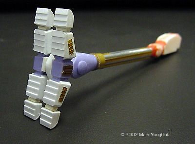
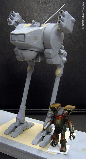
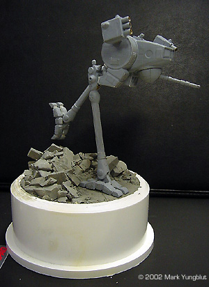
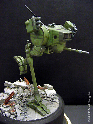
Here we see the finished model in its last coat of primer. The next step is to paint and build a base. Image: Here are the finished Launchers mounted to the shoulder brackets. Note also, that the final little parts have been built and mounted, including the sensor on the roof and the windows and hatches that need to be on the roof. Image: The completed mech, with elemental for size comparison (an "elemental" is powered armor suit big enough for one man) |
|
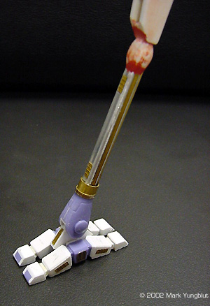
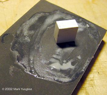
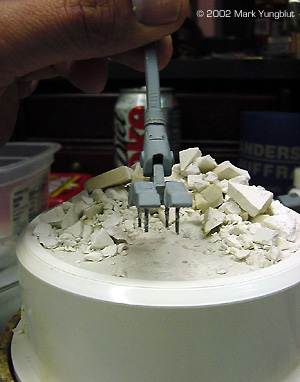
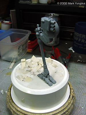
Painting and Mounting the Model on a Base I decided to build the base for the model before starting the paint job on the mech. I started by purchasing a PVC plumbing bushing, as the main part of the base. This would act to elevate the model a few inches, and the bushing would be mounted on a marble vase base. The first step was to create a dam and seal the hole that is part of the bushing. I did this by cutting a circle in .04 plastic. This was set down against the lip that is on the inside of the bushing. I then glued it in with a liberal amount of 5 min epoxy. This acted as a seal to prevent any plaster from leaking when it was poured. What I had in mind for the base was to have a city type rubble scene. I gathered some rubble that I created by buying a Woodland Scenics retaining wall and cutting it up. I placed some of the rubble that would be the bottom layer in the well created by the dam. I then poured fairly thin plaster of paris in the well and let it set up. Before the plaster was completely hard, I took one of the feet and pressed it slightly into the surface. This would aid in making the foot look as though it was in the scene as apposed to just off the surface. I let the plaster dry thoroughly, and then added additional rubble. I also scribed some expansion joints into the flat area.The next step was to put mounting pins in the foot that will touch the ground, and drilled corresponding holes in the base. To add additional strength, I added a piano wire main pin that went down the middle if the foot and up into the leg. This allowed me to make the mech removable from the foot for transporting it to shows. Once this work was done, it was time to paint the plaster base and rubble. I used Floquil concrete as a base coat, and thinned it 20% to make it more of a stain. This allowed the paint to penetrate further down into the plaster. When that was dry, I gave the entire rubble area an oil wash of Payne's gray oil mixed with a little black and burnt umber. The next day, I dry brushed progressively lighter shades of the concrete until I was happy with the shading and contrast. At this point, I masked off the rubble area, and spray-painted the rest of the base with Krylon flat black. I was then ready to finish the mech. |
Image: The pins in the foot Image: The final location of one of the legs relative to the base Image: The mech in its final pose on the base |
|
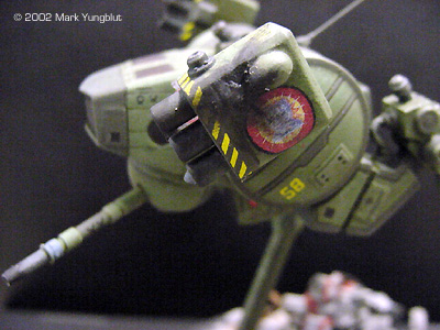
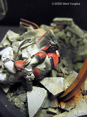
Image: Here is the mech with the initial layer of paint. Image: The Locust with the base color dry brushing complete, and the USMC green trim color applied. Note that I added bent steel beams and some rebar to the rubble. This was washed and dry brushed with rust colored enamel. Image: The battle damage was airbrushed and enhanced with pastels Image: As a final touch, I added a destroyed Clan Elemental (power armored trooper) to the top of the rubble pile |
I decided to paint the Locust in a green paint scheme depicting a mech that is pat of the 1st Federated Suns Armored Cavalry. I started this by painting a base coat of Humbrol olive drab. Once this had dried for two days, I gave the entire model a wash of dark green mixed with black oils. This was allowed several days to dry, before I started with the drybrushing highlights.
Once the oil wash was dry, I gave the entire model a shot of Humbrol clear matt to seal the oil wash. I then started to dry brush progressively lighter high lights over the entire model. Once the shading and contrast were at an acceptable level, I painted the trim green in Humbrol USMC green. This was dry brushed as well. I allowed the model two days to completely dry before I gave it a clear gloss coat for applying decals. John Lester was kind enough to make some decals from artwork that I provided, so the proper Fed Com markings were applied to the missile launchers and other parts of the mech. I also had a unit nickname decal made that depicts a hand with a scrub brush and a red circle with a slash through it. Above and below this it says "The Great Unwashed". Additional decals such as warning stripes and aircraft type maintenance markings were then added. These were allowed to set and then the model was coated several times with Humbrol matte finish. When the finish had dried, I weathered the model, adding battle damage, scrapes, and scratches with silver. I also added gray pastel dust to the base and the lower portion of the legs. So There You Have It ..... Scratch building a model is neither a "black art" that can only be mastered by a few, nor something that requires a $10,000.00 shop to accomplish. There are a variety of techniques that can be used to build quite effective models using the tools you already have. The important thing to remember it to try to plan out as much of the build as you possibly can. This does not mean you need to have extensive plans to build from, rather that you plan out the steps that will need to be taken in order to build the model. Most of all - don't be afraid to try! Learn by doing - and practice, practice, practice. |
![]()
This page copyright © 2002 Starship Modeler™. Last updated on 28 June 2002.
![[The inspiration]](my_scratch/Picture01_lil.jpg)
![[And so it begins]](my_scratch/Picture05_lil.jpg)
![[Click to enlarge]](my_scratch/Picture08.jpg)
![[Click to enlarge]](my_scratch/Picture10.jpg)
![[Click to enlarge]](my_scratch/Picture17.jpg)
![[Click to enlarge]](my_scratch/Picture22.jpg)
![[Click to enlarge]](my_scratch/Picture24.jpg)
![[Click to enlarge]](my_scratch/Picture27.jpg)
![[Click to enlarge]](my_scratch/Picture32.jpg)