
|
By Steven Jochums - images & text © 2013
|
![[Please click to enlarge]](sj_ssv_40.jpg) |
|
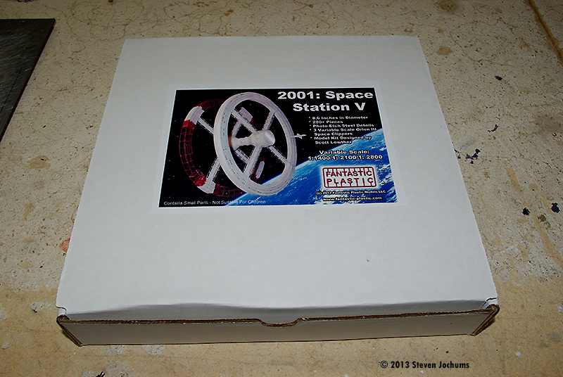
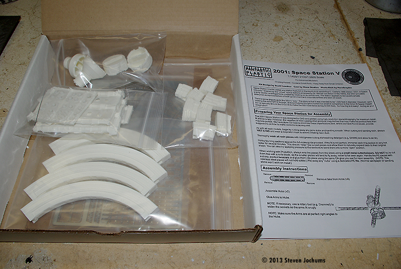
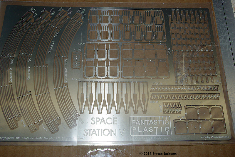
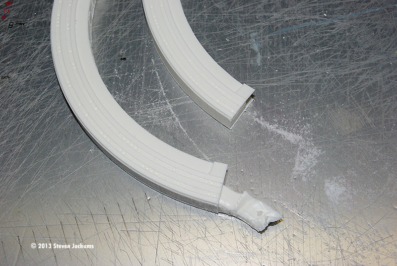
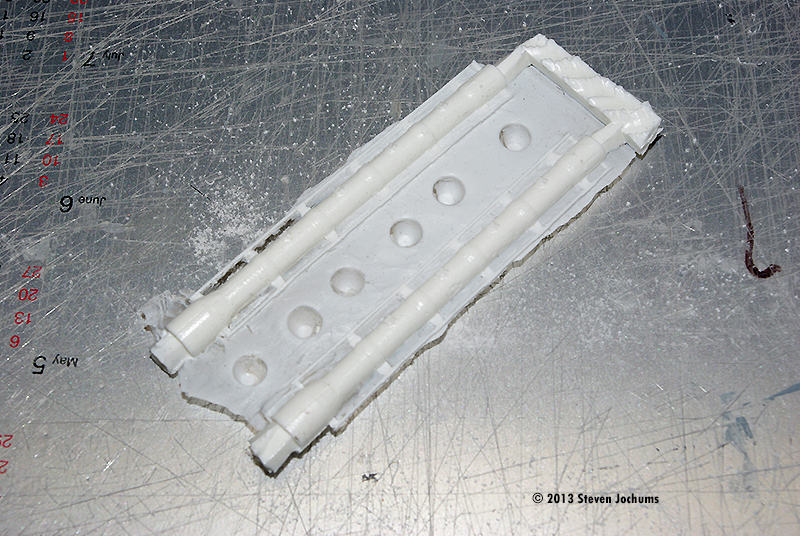
Image: The box Image: What you get Image: Photo-etch sheet Image: Mold stubs on the finished ring Image: There is a lot of flash on the ring support tubes Image: Cleaned up
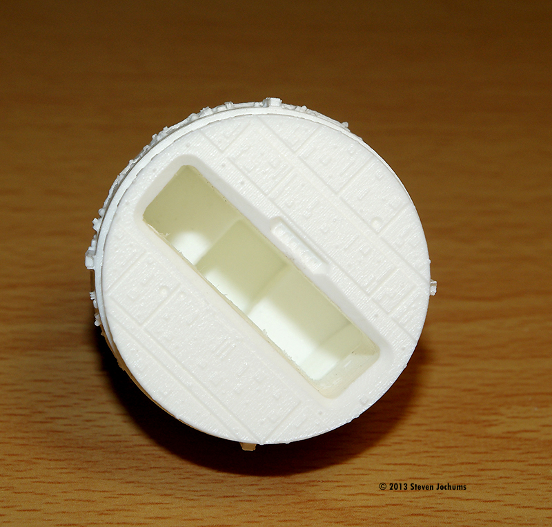
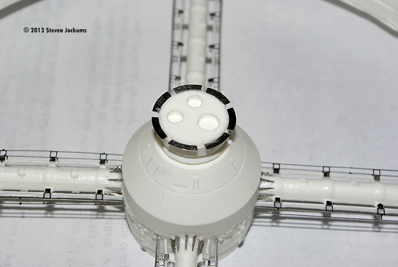
^ The hub sections are keyed to each other Image: The other hub Image: Docking chamber
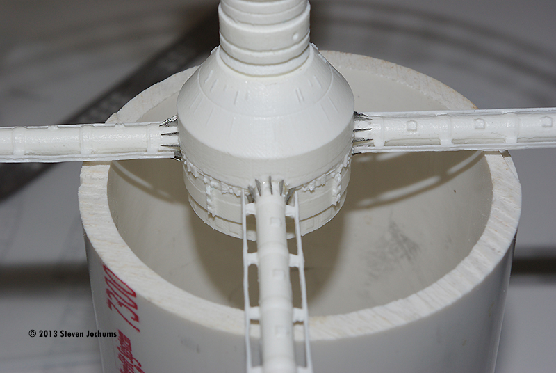
^ You will need to open up the sockets in the hub Image: PE support flanges
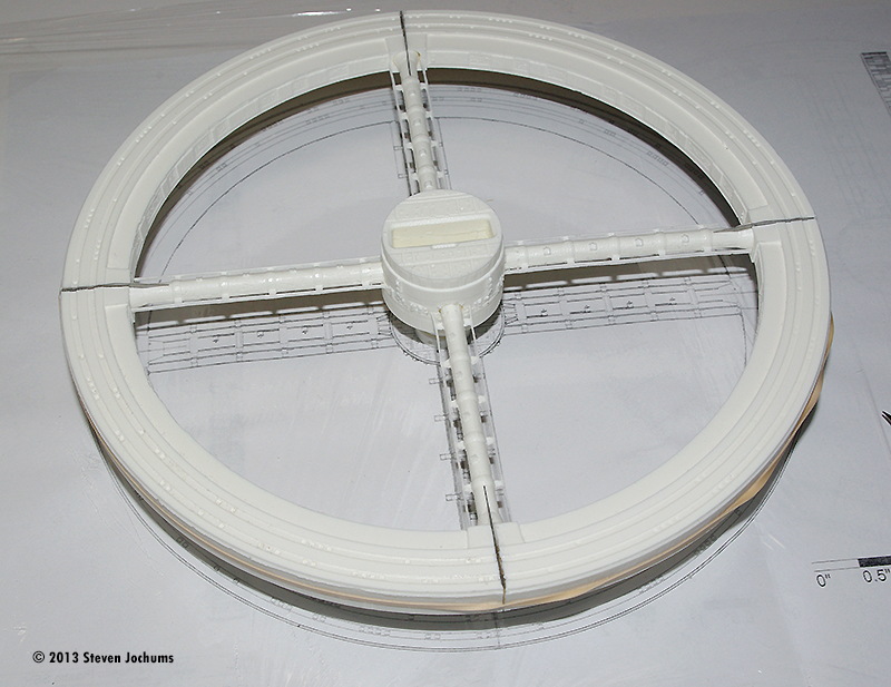
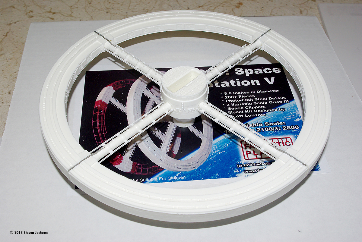
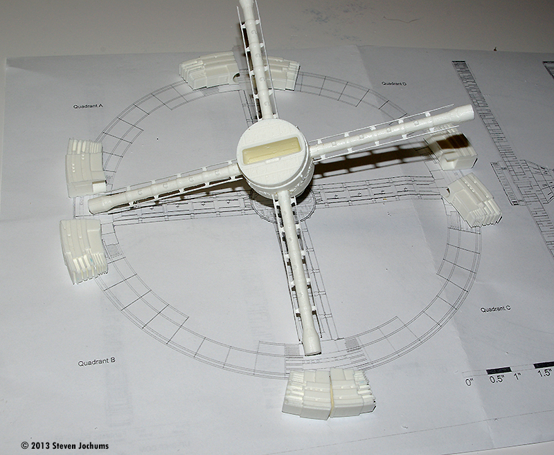
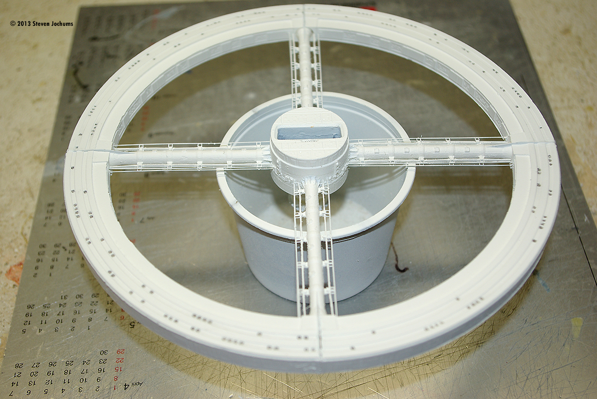
^ Assembling the "completed" ring sections Image: First 'wheel' as the glue is setting up. Image: Checking against the plans Image: Starting on the "unfinished" rings
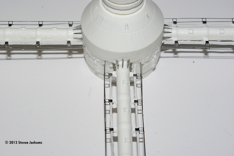
^ Alignment is critical here Image: PE gussets
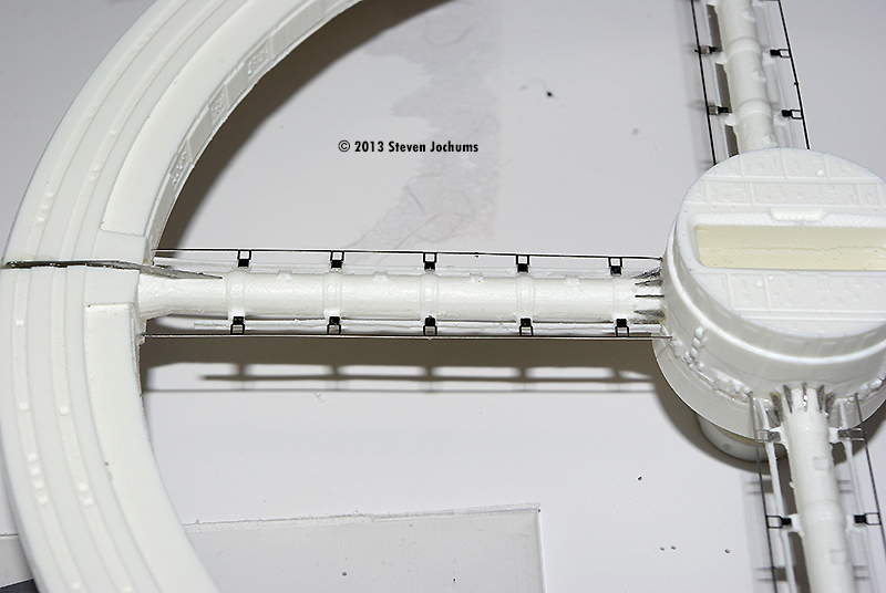
^ Placing the gussets Image: Gussets in place on one hub section Image: PE electrical runners Image: Placing them requires patience and a light touch
^ Start at the middle and work towards the ends Image: Radiators
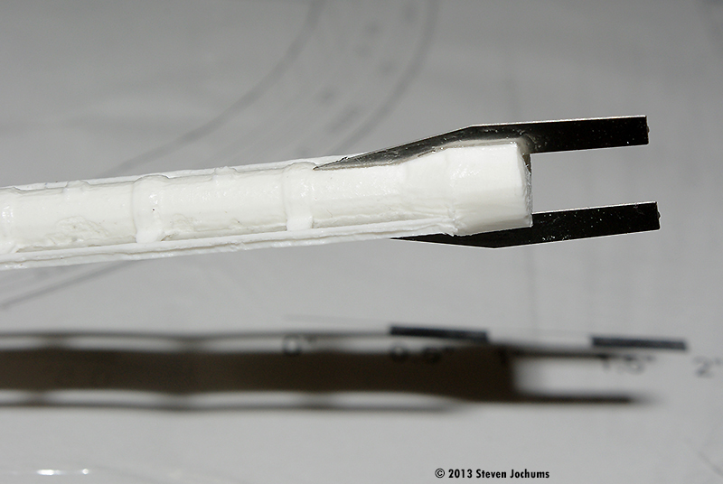
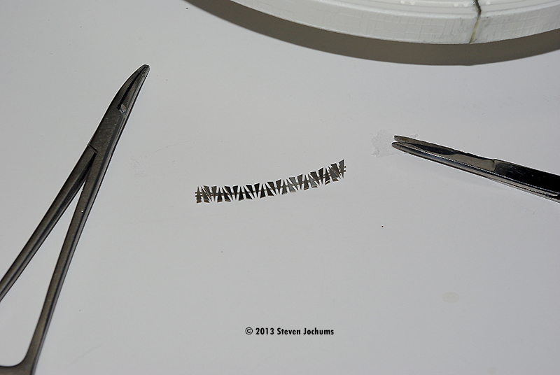
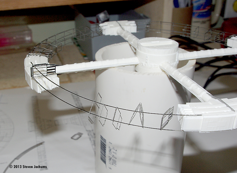
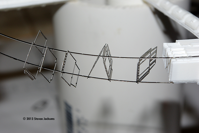
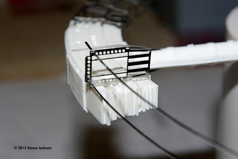
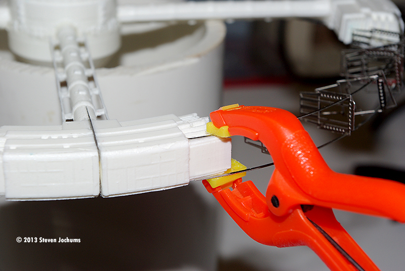
^ Starting the unfinished ring section Image: Affix the rails at one end, Image: String the frames on the rails Image: Closeup Image: Clamp the other end as the glue cures Image: The weight of a utility blade keeps the long rails in place as the glue cures
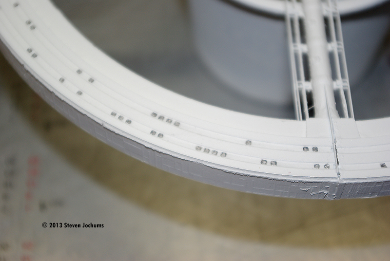
^ Finished rail sections Image: Finishing up the gussets... Image: ... and electrical "rails" Image: White base coat Image: A pencil was used to 'color' the windows Image: Painting the rails
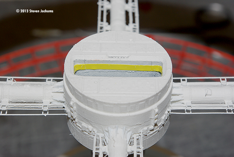
^ Mostly done Image: Docking stripe
^ Orion on approach
^ Done! |
Fantastic Plastic's Space Station V from 2001 - A Space Odyssey was a long awaited kit. Except for the Axis 4 Christmas Tree Ornament described in this section of SM, I knew of no other model of any kind produced on this subject. Now, through Alan Ury at Fantastic Plastic, it's here, but he had help. The kit was designed from CAD drawings of the station done by Scott Lowther. Mana Studios does the resin work and ParaGraphix does the photo-etched parts, which are the first I've seen made from stainless steel. You'll be grateful for this material choice later on. What You Get The kit arrives in a simple white cardboard box with Ziploc bags containing the part sets. Hub sections, "finished" ring sections, "unfinished" ring segments and the ring support tubes are all sorted into groups. The three variations of the Orion Space Clipper are tucked in with the support tubes, along with the steel support wire section that will be used to place it in front of the docking aperture. The PE parts are all in their own bag, taped onto a cardboard support to remain flat and undamaged during shipment. The kit also provided "spares" of the support tube gussets, which as you will find is a good thing. Getting Started The sections of the finished ring have large molding spurs still affixed to them, which must be removed and sanded clean. There is supposed to be a slightly raised center section where the ring sections will be glued together, and a slight recess on the edges so the PE tube flanges can slip into place after section-tube assembly, but not all of the sections have good relief in these areas, so I had to change my assembly process - more on this later. For now, I trimmed and cleaned the section ends. The ring support tubes have an amazing amount of flash on them, as well as molding runners on both ends. All of this junk needs to be cleaned off, and with eight tubes, this takes time - like everything else in this model. You cannot try to rush this build, so don't get impatient here. I used a fresh, sharp hobby blade to trim off the majority of the flash. Then I used the knife to gently clean inside the supported "electrical runners" that run along both sides of the tubes. A razor saw was used to take off the end runners. The hub sections are matched to each other, so be careful which parts you try to fit together. The inner hub sections have recesses that run around the outer edge, into which the outer section will fit. The problem is that there are large molding features which must be carefully trimmed and sanded smooth, in order to get a good fit between each inner and outer halves of each section. There is a definite match in the shape of the docking bay, which is the key to telling whether or not you've put the right pieces together. Building the Core When properly mated, there should be a Y-shaped docking chamber formed by the mated set, with continuous floors and walls. The creation of the two completed hub sections was the first big step. The manual says that you will need to open up the sockets in the hub to properly accept the support tubes. The manual is not clear, however, on how far into those sockets the tubes should go. Look very carefully at the instructions at this point and you will find that the is a "level" on the base of each support tube where the grooves for the gussets "start," which is intended to show how far into the hub the tube should go. The very bottom molded supports for the electrical runners are also supposed to be trimmed off at the tube surface to the end of the runner. This is to allow for the curvature of the core to meet the runners on both sides. Based on my experience, the runners are still too long at this point, and very careful trimming is needed to get the right length to match the insertion depth of the tube and the hub. If they're done right, the grooves for the gussets should match the markings on the molded flange on the hub socket and the electrical runners should just touch the core surface and run straight up (no bends) and the tube itself should be perpendicular to the hub in both axes.One way to cross-check for proper tube length would be to use a divider to copy the distance from the full -size drawing provided with the kit to the assembled length of the tubes. With all four tubes in place on the short hub section (the one for the finished ring), I tried to do some trial fits of the ring sections. It is important to use the full-size drawing to make sure you have the ring section arranged properly, based on the locations of the windows on the ring section. Then, you can pick a spot to start. I tried starting on the A-D ring section interface (top), but found that the ring sections were not lining up with the next successive ring section and support tube end properly. When checked against the full-size drawing, they appeared to be "too curved." It was then I found the answer to this situation on the front page of the instructions. Alan says that after molding, the resin may cool and curve inward slightly, preventing a good fit. If this is so, you will need to put the section into "very hot water," near boiling point, for about three-minutes so to slightly soften the plastic, and then gently bend them back into shape, dipping them into cold water to make them "set." This is all good, but what's to keep them from curving incorrectly during cool-down? I chose to tape the full-size drawing to a piece of "foam core," cover that with Saran Wrap and use seamstress' straight pins to hold the section in the curvature of the drawing. I did this with all four pieces, allowing them a full day to cool in the locked state. The fix works, just take your time. Because of the problem with ring section end feature I mentioned earlier, I chose to glue the PE support flanges onto the tubes first, using the molded grooves as guides. Once they were set, I brought the ring sections into position, emphasizing on one ring-tube junction at a time. A small barrel sander drum in the Dremel was used to adjust the tube sockets in the ring sections, in order to get a good, straight fit. The ring sections were locked in place with superglue (ACC). The slight gap at the top outer edge of the ring can be filled in with putty and sanded smooth. Once all four ring sections were in place, a rubber band was placed around the circumference of the ring to act as a "web clamp" and draw the sections together while the glue cured. As you will find, the full-size drawing was always a valuable reference for progress. I then turned to the long hub section, the four support tubes and the eight ring "segments" and worked to repeat the previous lessons with the "unfinished ring" assembly. Because of the open stainless steel structure that will be added to them, it is critical the make sure that each ring segment-support tube system is perpendicular to the hub and in-line with each other. This means additional care of adjusting the tube sockets on the ring segments in order to get them lined-up with each other. Photoetch This was the point where I went back to the big ring and worked to place the triangular-shaped tube gussets around the base of the tube at the hub socket. There is a definite order for these parts, as shown by the instructions. I chose to work on one "part number" at a time, i.e. doing all Part 28's first, then all Part 29s, then all Part 30s, etc. When these small (and I mean small!!) parts are removed from the PE sheet, they typically carry a point of metal from where the PE parts join together. Removal of this material requires that you hold the part in the very tips of a forceps and use the small Dremel grinding drum to clean off the excess - very gently!! Otherwise, you will "launch" the part out of the forceps jaws to God knows where. This use of the Dremel to clean off any excess metal runner is applicable to all PE parts of this kit, which is another reason this is not a kit for a beginner. The gusset is then placed into the tip of the forceps so that the 90-degree portion of the part is facing out from the claw-tips. The jaws should be at bare "finger-tip" pressure holding the part. A very light film of superglue (ACC) is placed into the location groove on the tube. Then, the "root" of the gusset is placed against the groove and the claws are released, leaving the part in place. It's a real matter of touch to get this right. If you miss, the part will fall over and you will need to remove it, clean off the ACC and try again. As there are 10 gussets on each tube base, this will require extreme patience and a light touch. Once the gussets are set, you can add a very small amount of superglue to them to permanently lock them down. Next to be added were the PE electrical runners, which are applied to the molded runners along each side of the support tubes. There are two PE runners, one front, one back, for each molded runner - a total of sixteen per ring assembly. Getting a scissors or metal cutter into the narrow gaps on the sheet to free these parts is near impossible. I found that a thin Dremel cut-off wheel (about 1 mm thick), with very gentle pressure worked best. Great care should be taken when placing these PE parts on the tubes to get good alignment between the "support blocks" on the PE parts and the supports of the molded runners. The length of the PE runner also needs to be trimmed so that each end contacts the appropriate location on the ring and on the hub. Once the length is right, it's best to start from the middle, setting a couple of locations and then working towards the ends, in order to maintain good alignment. The last assembly step for the finished ring system is adding the seven radiator parts to the groove that runs around the back edge of the hub core. Unfortunately, there is no guidance on the model or in the manual as to proper spacing between each segment. Trial and error reveals that about 2 mm of space between each segment is correct. Assembly of the PE tube gussets and electrical runners was not completed on the unfinished ring system until all the PE ring structures were completed and installed. I did not want to bump into, or bend them during this work, so I saved them almost for last. The instructions work closely with the full-size drawing in order to provide complete location familiarity with the 'unfinished" ring parts. Each unfinished ring section is made from a system of four long PE rails, which thread through slots on the largest sectional parts or run within the smaller inner sectional parts. This is the primary structure. Another set of long rails go along the outside edges on the bottoms of all sectional parts. These are hard to locate until the prime structure is done. Shorter upper rails run from the outer sectional parts to the resin segments, enhancing the "unfinished" look. The PE rails come off the sheet in the following order: the first two are the bottom-outside-edge rails, the next two are the inner bottom rails, the next two are the inner upper rails and the last two sets of two are the short end-section upper rails. According to the instructions, the intent is to build-up these sections separately and then place them onto the resin segments. I found this approach to be somewhat problematic, as the ring runners did not want to "sit still" on the structure sectional parts while the glue set. While I did complete rear "Segment A" in this manner, I found - again by trail and error - a better way. By first fastening the lower inner rails to their location on the resin segment, on only one end, you can support the "open end" and thread the sectional pieces along them in the order specified in the instructions. Now, you affix the open ends down to the opposing resin segment. Then, the two inner, upper rails can be threaded through the sectional parts and locked into place on each resin segment. This allows you to now properly locate each section part on the indentations provided on the rails and get proper alignment for gluing. Then, the short upper rails can then be placed on each end of the assembly. Once this structure in completed, you will find it much easier to locate, support and cement the long outside rails to the locations on the sectional parts and resin segments. I also found that the light weight of an utility blade was just right to hold these rails in position while the ACC joints set up. With all four PE ring sections completed, I returned to the chore of placing the PE tube gussets and electrical runners to complete the rear ring assembly. Finishing The front and rear assemblies were supported over the paint table and given two full coats of Flat White enamel as the base color. A Pentel drawing pencil with 0.5 mm HB lead was used to do the windows of the rings, running the graphite into the window openings. Then the PE ring sections were hand-painted International Orange, which was my choice based on how other open steel structures are painted during construction. The movie is not very helpful is establishing the "correct" color, as the lighting is done for visual spectacle and not for color correctness. Some might paint these plain old Red. Some might choose Rust, but that doesn't seem to work for me, as there is no oxygen in high Earth orbit to create oxidation. Anyway, they appear reddish in the film, and open metal structures are typically painted International Orange to be seen. (Image 36) A light wash of acrylic enamel thinner and flat black in a 50 to 1 ratio was brushed over the skin to create relief of all the molded surface details. A 2 mm wide strip of yellow striping tape was added to the openings of the docking bays in order to represent the target lighting seen on the film. Then the entire model was coated with Krylon Satin Finish to protect the detail and seal the finish. Finishing Touches The last detail was the addition of the little Orion Space Clipper approaching the docking bay. The kit comes with three sizes of Orion Clippers, so you can decide what "scale" your station model represents. I guess there is still "debate" among aficionados about the "actual size" of the station, which is why the choices were provided. I chose the smallest Orion, placing the model at 1/2800 scale, which means that Space Station V would have been 2000 feet in diameter. To me, looking at the approach scenes in the movie, this size looks right to me. Using very fine-tipped makers, I placed the blue "PanAm" circles on the sides and the black ducts of the engines. I used my Pentel pencil again to create window detail relief and a front windscreen across the nose. The little Orion was then secured to the steel wire support provided, which was painted Flat Black, and secured to a hole drilled into the face on the lower edge of the bay opening. Because of the location of the drilled hole, I had to offset the Orion a bit to get it lined up with the docking bay. Conclusions Without question Fantastic Plastic has created one of the most challenging and beautifully detailed 2001 models to be sold thus far. To paraphrase an old US Marines ad, "the challenge is great, but the rewards are greater." To actually have Station V now sitting above my cache of other 2001 models is s genuine thrill, and one I never thought I'd see. While it's rumored that other Space Station V kits "may' become available, this is currently the only one I have found, and while there were problems with mold qualities (and it seems all resin kits have their issues), with Alan's help via e-mail, none of the trials encountered here were insurmountable. Any proficient space modeler would be proud to make this part of their collection. They will have earned the right to be proud, building Space Station V. |
Please note that the opinions expressed in this article are those of the reviewer.
Read other reader's reviews of this kit ![]() Submit your own review of this kit.
Submit your own review of this kit.
![]()
Go back up | 2001 Index | Starship Modeler Home | Site Map | Feedback
This page copyright © 2013 Starship Modeler™. First posted on 20 June 2013.
![[Please click to enlarge]](sj_ssv_07.jpg)
![[Please click to enlarge]](sj_ssv_10.jpg)
![[Please click to enlarge]](sj_ssv_12.jpg)
![[Please click to enlarge]](sj_ssv_16.jpg)
![[Please click to enlarge]](sj_ssv_18.jpg)
![[Please click to enlarge]](sj_ssv_22.jpg)
![[Please click to enlarge]](sj_ssv_24.jpg)
![[Please click to enlarge]](sj_ssv_30.jpg)
![[Please click to enlarge]](sj_ssv_36.jpg)
![[Please click to enlarge]](sj_ssv_38.jpg)
![[Please click to enlarge]](sj_ssv_39.jpg)