
|
By John Martin - images & text © 2006
|
"What a piece of junk!" --- Luke Skywalker "She may not look like much, but she's got it where it counts." --- Han Solo |
|
|
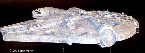
The fictional Millennium Falcon was portrayed by a number of studio miniatures and full-size sets. The first model of the Millennium Falcon built for Star Wars (Episode IV) is a massive prop, with a length of 173 cm/68 inches (Star Wars Chronicles, p. 95). Portrayed on screen, its maneuverability is the result of motion-control camera work. For The Empire Strikes Back, a smaller version was built that would be easier to control in action scenes, such as the famous asteroid chase. |
|
The length of this model not given in Chronicles, however various studio-scale internet websites list the model as approximately 82 cm/32 inches. This would make the ESB Falcon approximately half the length of the original, and, assuming they were made from similar material, approximately 1/8 of the weight. Although the smaller Falcon was incredibly detailed, some close-up shots in The Empire Strikes Back were of the larger Falcon. The smaller Millennium Falcon was used again for Return of the Jedi. |
|
|
^ Central core in place Image: Cockpit interior Image: Cockpit pieces Image: Turret plating
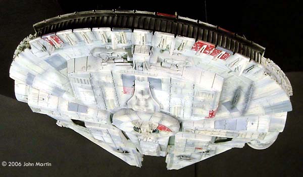
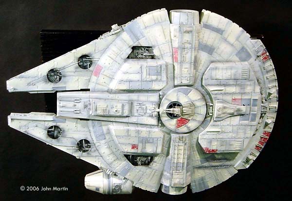
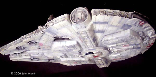
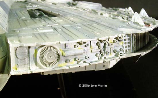
^ Bottom test fit Image: Topside, testfit Image: Base coat and preshading Image: Cockpit tube plans (PDF) Image: Docking Ring plans (PDF) Image: Engine Grill plans (PDF) Image: Forward Landing Gear Box plans (PDF) Image: Sidewall Detail plans (PDF) ^ Topside Image: Top view Image: Port side Image: Head-on view ^ Underneath Image: Under the bow Image: Below and behind Image: Bottom view Image: Underneath, portside ^ Cockpit area details Image: Under the cockpit details Image: Cockpit access tube Image: Sensor dish and portside details Image: Port quarter sidewall Image: Port sidewall Image: Starboard quarter sidewall ^ Engine deck detail Image: Gun turret Image: Hull damage Image: Landing gear boxes Image: Machinery bays Image: More machinery bay detail |
Many scenes, however, that required forced-perspective, used smaller, less-detailed studio models. A two-inch-long version is shown on page 181 of Chronicles, and a ten-inch-long version was seen along with the 68-inch model displayed at the Magic of Myth Smithsonian tour. It is also been rumored that one of the 18-inch store-bought model kits was used on film. The Falcon was also represented by two full-size studio set pieces, and at least three interior sets. The exterior of the Falcon seen on Mos Eisley and in the Death Star hangar was only partially built, with the rest (mostly the port side) provided by a matte painting. For The Empire Strikes Back, a complete Millennium Falcon was built for the Hoth Rebel base. For scenes in the interior of the Falcon, sets of the cockpit, main hold, and gun turret were built for Star Wars. The sets were updated for the later movies. An extensive overview of the Millennium Falcon has been provided by Robert Brown, which has been archived here. Mr. Brown discussed the history of the ship as the script of Star Wars developed, possible �in universe� functions for various components, and the size contradictions as provided by various �canon� sources. He also analyzes various cutaway/cross-section plans and compares them to on-screen evidence. The Ertl Kit �You came in that thing? You're braver than I thought.� -- Princess Leia The original MPC Millennium Falcon model kit was first available in 1979, and was reissued for The Empire Strikes Back and Return of the Jedi. According to Tomart's Price Guide to Worldwide Star Wars Collectibles (Second Edition, Sansweet and Tumbusch, p. 122), the model has been available in four packages:
A cutaway version, which used most of the parts from the original version, was also available from AMT/Ertl. Recently (as of 2006, when this was first written - Ed.) both the original kit and cutaway versions have been available, in new packaging, reissued from AMT/Ertl. (As of late 2015, a new kit of the same size was issued by Revell, which builds into either original trilogy or SW:tFA versions. It's available here). Built straight from the box, the Ertl kit is impressive, but not overly detailed or accurate. To the casual fan, the kit is recognizable as the Millennium Falcon. However, there are a number of structural inaccuracies that make it look not quite right. The most glaring is the over-sized sidewalls. This is one of the factors that give the kit a flat, �hockey puck,� shape. The cockpit and tube are too small proportionately to the hull. The dish is too big. The sidewalls, engine deck, and most of the hull lack the appropriate details, or �greeblies.� I had first built the Ertl kit in the spring of 1980, shortly after receiving it for Christmas. I will not lie: my first pass was really sad. The huge gaps between the hull sections and sidewalls were filled with toilet paper soaked in glue. Only a few panels were painted Testor's gloss red and gray. I never even tried the kit lighting; I just painted the engine bright gloss green. True, I was only eleven at the time, but even then I knew I could do better. However, I must confess that I spent more time playing with this Falcon than the Kenner version, which I also received that Christmas. Years later (in 1995 in fact), I came across an article in Sci-Fi Modeler by a gentleman named Darren Peters. In the article, Mr. Peters detailed a number of structural changes he made in order to make the kit more accurate. Most significantly, he cut the sidewalls to a smaller height, rebuilt the cockpit cone docking rings, and built the forward landing gear bays (which were originally added to the �real� Falcon sometime after the Battle of Yavin). When I came across the article, I had been trying to improve the AMT/Ertl X-wing kit, and had just finished the Star Trek: Voyager special edition kit. I thought that it was time to add an accurate Falcon to my shelf. All it required was a little scratch-building, right? Naming Conventions In order to be clear in the discussion, I will borrow the terminology used by Robert Brown.
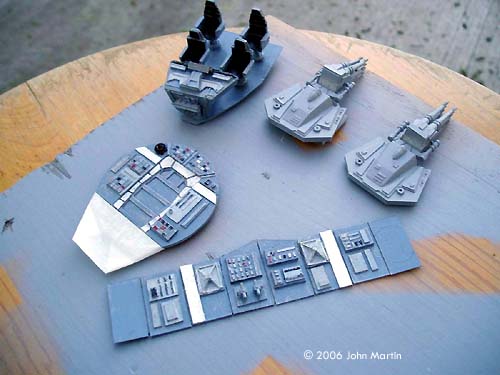
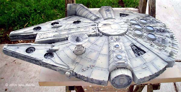
Overall Shape Built out of the box, the MPC Falcon is �flatter� than the studio models. In order to increase the apparent curvature of the hull, I did three things. First, I cut the kit mandible sidewalls to a height of 1.4 cm, and the saucer sidewalls to 1.6 cm. (Eventually, I replaced the sidewalls altogether. More on this later.) This addressed the most blatant flaw of the kit. Second, I built a cylinder from plastic sheet that would hold the center portion of the upper and lower hulls away from each other. The diameter of the cylinder was 8.5 cm (slightly larger than the gun deck, part number 37) and the height 6.6 cm. The cylinder was made by rolling sheets of plastic around discs cut at a diameter of 4.2 cm. Space was provided for the gunwells. This was placed in the center of the hull sections and kept the center of the model at the correct height. Finally, to allow for the upper and lower hulls to flex, I cut off the molded-on docking arms. The upper and lower sections of each were saved for later. After I taped everything together and checked the curve of the dish, I used sheet styrene to cover the trapezoidal holes left in the hull. Landing Gear Boxes As mentioned above, one major structural difference between the original ANH Falcon and the ESB Falcon is the addition of two forward landing gear boxes. These were added after correcting the curve of the hull. The width of the boxes was determined by using a head-on picture, printed and enlarged on a photocopier to the same size of the model. As with most of the rebuilt structures, I first build test versions for the boxes from construction paper. The bottommost face of each box was first drawn and cut out. These were roughly trapezoidal in shape, except that the angled side was curved to match the hull. The sides of the boxes were determined by using a contour guide to find the curve where they would touch the hull, and by attempting to match to the sides of the aft landing box assembly. After getting the right shape, the boxes were then built using sheet plastic. Before they were attached to the lower hull however, the mechanical bays (parts 22 and 23) needed to be moved. New holes were cut in the hull about 2 cm out from the original kit cut-outs. Plating and details were added after the boxes were mounted to the hull. According to my references, the outer sides of the forward gear boxes form a line with the outer sides of the aft gear box, so I widened the rear box about 1 cm on each side. Like the forward boxes, this was accomplished by first using construction paper, and then sheet styrene. Docking Arms Originally, I had intended to build each entire docking arm and slide them into the hull cut-outs port and starboard. I imagined that this would give more structural stability to the hull sections. However, I was having a difficult time cutting the hull in order to match the curve to the docking arm. I decided instead to fill in the wedge-shaped space cut out from the hull with sheet plastic (see above), and then build the docking arms on top of the hull. The upper and lower sections were taken from the kit, but the forward and aft slanted surfaces were built from sheet plastic, including the plating and details. Octagonal plates on each end were cut from sheet plastic, and the upper and lower parts of the docking arm were glued to it. This allowed me to align the upper and lower surfaces without �eyeballing� it, as I would have done if I had directly glued them to the hull sections individually. |
|
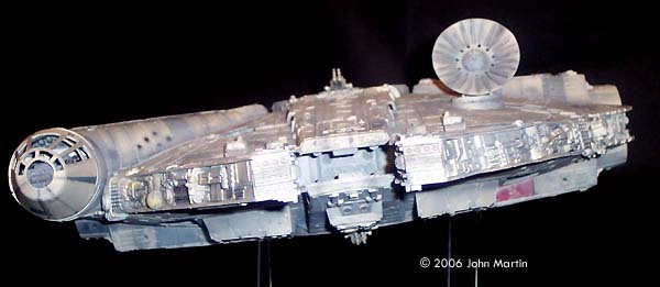
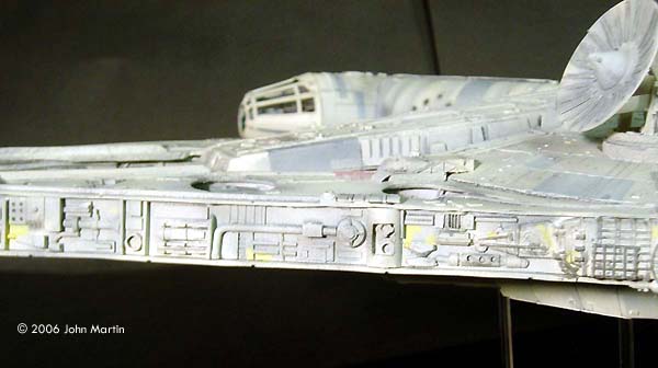
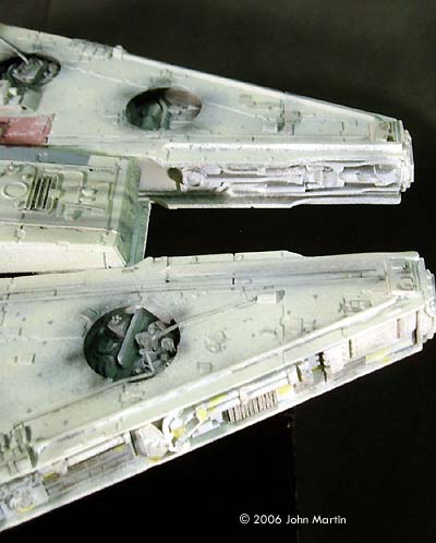
The docking rings were completely scratchbuilt. According to my measurements, the docking ring should be 4.8 cm in diameter at its widest point (attached to the docking arm) and 4.4 cm in diameter outboard. (This refers to the edge of the ring. The outer wall is inset slightly.) To make each ring, two circles were cut from plastic. Two trapezoidal pieces were cut, and glued together at right angles. The circles were then glued to each side of this �X.� The curved sections that would make the frustum were cut and wrapped around this structure. Sections of sheet plastic were then cut for the armor plates. The outer wall of the docking ring was then detailed with hexagonal plastic sections and various rods, strips, and parts from the spares box. On one of the plates of the ring behind the cockpit a chunk was dug out with a motor tool to simulate meteor or blaster damage. |
|
|
Sidewalls As mentioned, I originally intended to use the kit sidewalls with additional bits from the parts box. But, as more reference material became available, I decided to scratchbuild them, using the smaller ESB Falcon as a guide. I found fairly decent reference photos of the details along the mandibles and rear quadrants. |
|
|
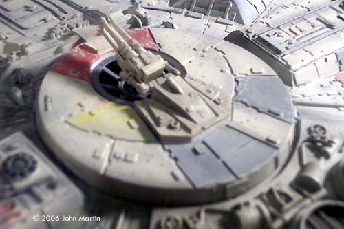
Using a draw program, I sketched out the rough size and relative placement of each of the �greeblies.� Rectangles were cut from sheet plastic, and the details were glued to them before mounting them on the hull. Bits of unbuilt kits that somewhat matched the various structures were used, but unfortunately most of the details needed to be scratchbuilt. Except for a small part of a 1/24 scale NASCAR model, the structures at the aft end of the mandibles (represented on the ESB model by a Porsche transmission) were scratchbuilt by sheet plastic. The dome slightly forward of the cockpit is the head of R2-D2 from the MPC X-wing kit. Because of the decrease in height at the sides, kit part #7 (upper and lower) that sits inside the upper and lower jaws was modified. The edges were trimmed such that the part would sit inside the jaw sections, and not on top of the edges. Part 68 (x2), between the mandibles, was not replaced, but was cut to the correct height. Gun Turrets The interior of the gunwells were scratchbuilt by cutting eight rectangular sections and attaching them to the octagonal back wall. The gun chair and targeting computer were included. Since very little is able to be seen in the completed model, there is not a lot of detail, but the walls do have different colored panels that give the impression of the original set. The quad guns were scratchbuilt using bits from the kit guns and sections of sheet plastic. The gun mounts were raised a little higher than stock by mounting them on thick sheet styrene before attaching them to the kit. Engine Grill I never decided until near the end whether to light the engine, cockpit, and gunwells, so clear sheet plastic from a broken poster frame was used make the engine exhaust opening. Vertical ribs were cut from sheet and spaced 0.4 cm apart in order to represent the engine grill. I eventually decided to not light the model for three reasons. First, I have no experience with lighting models and did not want to learn how to on this. Second, I was not interested in having a battery access door or an electrical cord running out of the hull. Finally, near the end of this build Fine Molds announced their 1/72 scale Falcon. Maybe I will try to light that one. This means, however, that I am not very happy with the engine grill. I considered painting a bluish-white strip, but in order to make that look accurate to the movie I would have to paint the engine glow around the engine light blue. I finally decided to leave the engine as it is. |
|
|
Cockpit and Cockpit Tube One major section of the kit that needed to be rebuilt was the cockpit and cockpit tube. Relative to the width of the model, the cockpit tube should have a diameter of 4.4 cm. A cylinder was built by wrapping layers of very thin sheet styrene around plastic discs cut to a diameter of 4.2 cm (to account for the thickness of the tube and plating). Of course, there are two sections of tube: the longer section that represents the passage from the main hold, and the shorter section that holds the cockpit. |
|
One could build these as a single tube, and then cut the tube (possibly using a miter saw) at an angle, rotate one section 180 degrees, and glue together. I decided, however, to build each section separately. Unrolled, the angled �cut� would form a sine wave, so I used a graphing calculator to determine the function, and then used a spreadsheet to calculate the height of the curve at each 0.5 cm. Then I drew the curve using a draw program, and cut it from construction paper. After a few test shots (I had originally used a tube diameter of 4.8 cm, which looked too big) I cut everything and fashioned it from plastic. I should probably mention at this point that most of my calculations for the diameter and placement of the cockpit and tube (and the front landing gear boxes) came from reference photos of the 68 inch Falcon built for Star Wars. Since then, more reference photos of the 32 inch ESB Falcon were available. It is difficult to tell, but it appears that the cockpit is in a different position and has a different diameter, relative to the rest of the hull. The cockpit canopy was built similarly to the docking rings. I determined the inner and outer radii and the angle to be cut. A structure was made (similar to what I had done with the docking rings) using two discs and two trapezoids. Layers of thin sheet styrene were wrapped around this, but unlike the docking rings, they were not attached. The forward part of the canopy was cut similar to the main part, except it was glued directly to the main canopy without building a form to wrap around. The outlines of the windows were drawn onto the canopies. Using a small bit in the motor tool, tiny holes were made along the inside of each edge. Then a number 11 blade was used to cut from hole to hole, and clean each side. Files and sandpaper were used in the final shaping. Small strip styrene was used to frame up each opening. The interior of the cockpit was added to the model after the final painting. The back wall was built from sheet plastic, and included the doorway/hatch. The cockpit floor was cut and scratchbuilt seats and instrument panel were added. The ceiling was built using eight rectangular sections glued to the inside of the tube. I decided not to include figures. |

|
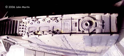
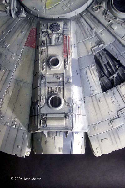
Engine Quadrant The detail on the kit engine deck, like most of the model, is a little sparse. Strips of styrene were placed along the inside circumference of the six engine vents. Other strips were added along the vent struts to build up the detail. Much of the molded-on detail at the rear of the engine deck was sanded off and replaced. Checking my references, I again raided the parts box to see if anything matched up. Various parts of model airplanes and helicopters ended up back there, but again most of the detail was scratchbuilt. |
|
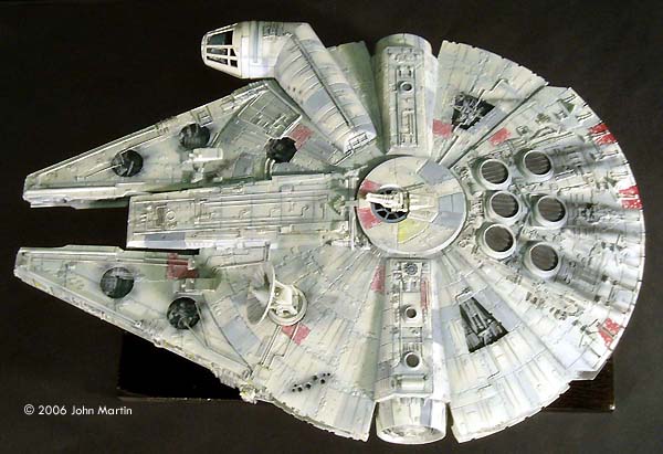
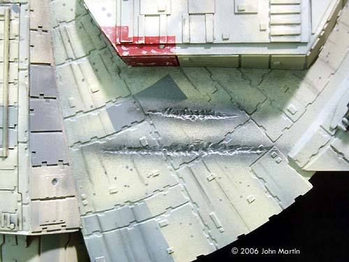
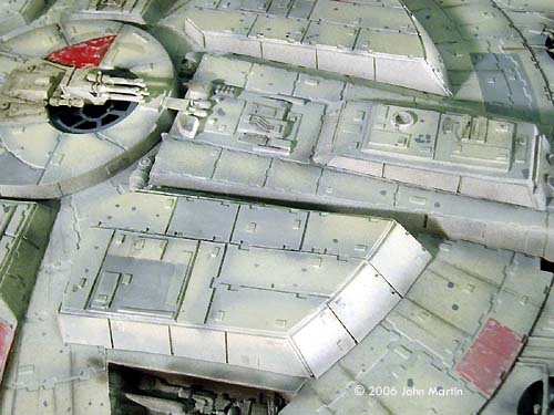
Hull Details Bits and pieces from the aforementioned parts box, along with strip and rod styrene, were used to �busy up� the thirteen mechanical bays. For each of the mechanical bays, the plastic around the hole was shaved to make the hull appear more �in scale.� In some places, some of the greeblies molded onto the hull that did not look quite right were sanded off. The �fins� along the inside mandibles were cut off. Various structures that are prominent on the ESB model were added, including the �A�-shaped tubing near the cockpit. The box devices on the top of the hull (on the dish near the mandibles) were removed and scratchbuilt to match the ESB version. The battle damage behind the dish and along the lower aft quarter was drilled and cut using a rotary tool. The massive �scars� on the lower port quarter were also added with a motor tool. Along the edge of the dish, small rectangles were cut out from the overhanging plates. Finally, many additional rectangular �chips� were added to the hull. |
|
|
^ Port docking ring detail Image: Port docking arm Image: Top of the mandibles |
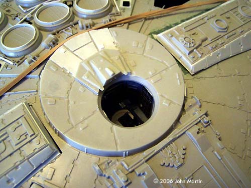
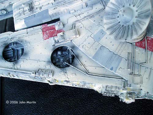
Dish The kit dish is too large relative to the rest of the model. Using a compass, a circle of the proper diameter was drawn inside the dish, and the edge was cut off with the cutting wheel of the rotary tool. Then the edge was sanded into shape, including the �flat� sections. The detail inside the sensor dish was sanded off, and replaced with strips of styrene. The center cone was built from sheet styrene, and filled on the inside with putty. This allowed me to drill small holes and place four small rods along the top, bottom, and sides of the cone. The dish supporting arms were also cut down, and built up with plastic to be thicker. Little bits and pieces from other kits were placed in the middle of the base (#29) to give a little more detail. Final Assembly Because of the number of scratchbuilt sections, test-fitting occurred quite often during the construction. When it seemed like a section was complete, it was attached to either the upper or lower hull pieces. The general order of completion follows. Detail sections were included at appropriate times.
|
|
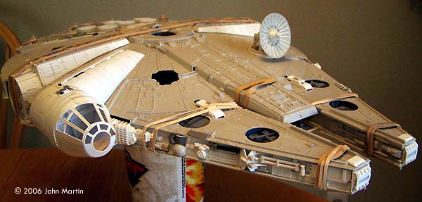
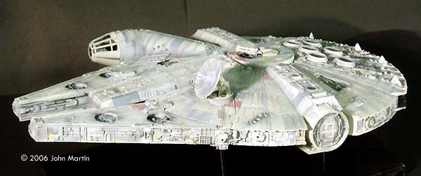
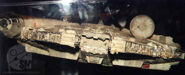
Painting and Weathering The completed model was first given a coat of gray automotive primer. At this time, some surface flaws, such as scratches from sanding, were addressed. Then the model received a coat of flat white. (White primer paint would have been preferred, but I never seem to find it in the stores.) The thin-line nozzle on the airbrush was used to pre-shade the model. The panel lines (between the armor pieces), structure joints, and greeblies were traced with flat black. At this time, the engine vents, docking arm screens, and mechanical bays were painted black and masked over. After quite a bit of research, I decided that the best base color would be camouflage gray (FS 36622) . This was sprayed over the pre-shaded model in thin, mist-like coats. Along the sides and the engine deck, I used very light coats, however, in places where I wanted the pre-shading to be more subtle, such as the armor plate joints, I used slightly heavier coats. Individual panels were masked off and painted using light ghost gray (FS 36375), dark ghost gray (FS 36320), or a custom brick-red color that I originally made for my 1/48 A-wing pair. After the panels were painted, a small brush and the base color were used to simulate paint chipping. The model was then given an overcoat of Future acrylic floor polish. After this had dried, black and gray artist oils, mixed with quite a bit of thinner, were used to bring out many of the details. After a day, I went over much of the wash with cotton swabs and small paper towel balls soaked in thinner. (As with my previous models, I have to give credit to Alfred Wong and his weathering article for guidance with this.) It was difficult not to overdo the wash. I continued to check my reference photos. After I was satisfied with the result, I used Testor's Model Master dullcoat to seal the oils and remove the gloss from the Future coat. Black and dark gray were airbrushed in various places to simulate exhaust, dirt, or blaster damage. The base coat was dry-brushed over some of the darker detail sections, notably the mechanical bays and rear engine deck. The streaks that radiate along the dish from the central core were added by pencil and artist's chalks. Finally, very thin coats of the camouflage base color were applied overall to bring it all together. |
|
|
Conclusion The model was built over a six or seven-year period. Often, I would take time to work on it, only to sit for an hour or two simply trying to wrap my head (so to speak) around how I wanted to build a particular section. It was put on the shelf and left alone many times. I should add that I completed a master's degree and started a family during this time. I know that my wife is glad that it (and the boxes of tools, plastic sheets, and paints required to build it) is no longer on the dining room table. |
|
|
I am proud of the final result. I accomplished the goal that I set out to do, namely build a more accurate model of my favorite spaceship. This required me to learn many skills as almost half of the model required some level of scratchbuilding. I am thankful for the advice given by the posters here at www.starshipmodeler.com , especially for the encouragement and praise along the way. References
|
Please note that the opinions expressed in this article are those of the reviewer.
Read other reader's reviews of this kit ![]() Submit your own review of this kit
Submit your own review of this kit
![]()
Go back up | Star Wars: Rebel Alliance | Starship Modeler Home | Site Map | Feedback
This page copyright © 2006-2015 Starship Modeler™. First posted on 18 August 2006. Last updated 18 November 2015
![[Please click to enlarge]](jm_mf/39_topfrwdport.jpg)

![[Please click to enlarge]](jm_mf/01_centralcore.jpg)

![[Please click to enlarge]](jm_mf/41_topportqrtr.jpg)
![[Please click to enlarge]](jm_mf/09_bottomstbd.jpg)
![[Please click to enlarge]](jm_mf/11_cockpittop.jpg)
![[Please click to enlarge]](jm_mf/16_enginedeck.jpg)

![[Please click to enlarge]](jm_mf/29_portdockingring.jpg)
