
|
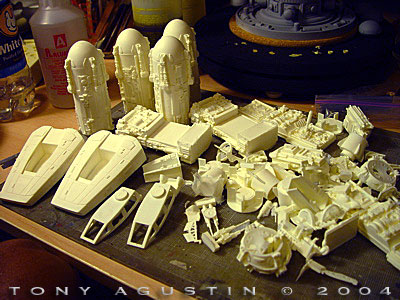
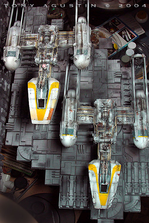
By Tony Agustin - images & text © 2004 In the early months of 2003, Scale Modeling Technologies (SMT) re-released their Star Wars Y-Wing in a newly refurbished 1/48 scale resin kit. I was very fortunate to purchase a pair of their Y-wing kits just before SMT's Star Wars vehicle line was abruptly ground to a halt by Lucasfilm Ltd. Kit Survey Like any resin kit that comes my way I like to spread out all the parts onto the workbench to do a visual examination of each and every part for flaws. I dry-fitted the parts to look for any kind of major/minor fit problem that might need to be taken care of. |
![[Click to enlarge]](ta_gold/DSC07373.jpg) |
|
Click any image to enlarge
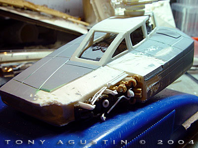
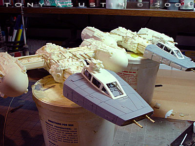
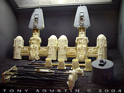
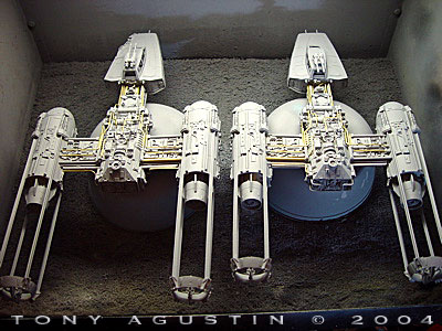
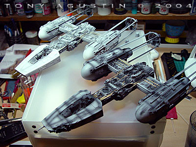
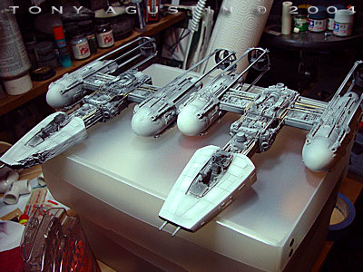
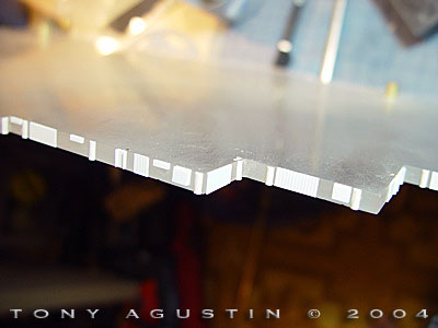
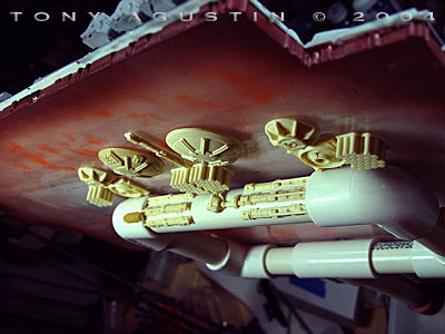
Image: The Y-Wing parts are laid out for inspection. Image: The old panel lines are filled in. Image: The new panel lines are scribed in. Image: The rear vector vanes are fixed up. Image: All four are now done. Image: All 16 of those odd details are now re-installed on each engine. Image: The exhaust ends are replaced with resin pieces. Image: Battle damage starts by cutting out a chunk of resin. Image: Surrounding areas are ground away and the interior dressed with tank parts. Image: The forward weapons are replaced with brass tubing. Image: The gun barrels are replaced with brass and styrene tube. Image: Myriad brass tubing just behind the unattached front cockpit fuselage. Image: More tubing slowly being installed one by one onto the main body. Image: The scribing and tubing is done on both Y-Wings. Image: The face is now attached and a new helmet is made from epoxy putty. Image: The pilot is done and the cockpit is dressed up with a new targeting computer. Image: The Y-Wings are washed and almost ready for priming in my paint booth. Image: The front Y-Wing is being Pre-Shaded with black. The rear Y-Wing is done. Image: Both Y-Wings are done and ready for the next steps. Graphics and weathering. Image: The markings are painted with Badgers 'Freak Flex' Acrylic paint. Image: More masking and painting of additional stripes for the engines. Image: Tamiya Medium blue is used to paint the Cockpit window frames. I use a dull #11 exacto blade and scrape-in scratches very lightly into the paint to reveal the gray primer underneath. Image: Additional panel variations are airbrushed in, and I again scrape into the paint for more weathering effects. Image: Weathering is done with grime and rust colors thru an airbrush or in small controlled washes with a paintbrush. Image: I scanned and upsized an old Finemolds X-Wing decal sheet to make decals for the R-2 and R-5 units. I printed them out on an Epson C80. Image: The droids are painted their appropriate colors and coated with FUTURE for the decals. Image: I make additional decals for the Pilot helmets. Image: A rebel pilot is finished and fitted into his Y-Wing cockpit. Image: Same goes for the other Y-Wing pilot. Image: The basic footprints of all 5 tile shapes are cut from thick styrene sheet. Image: More distinct structures are built up with laminated styrene. Image: All 5 tiles are completed. Image: Rubber is poured into each cell and allowed to cure for 24 hours. Image: Close-up of one of the tile molds. Image: A freshly pulled resin copy from the tile mold. Image: Tiles are cleaned up and washed. Just some of the 132 ‘usable’ tiles that were made. Image: The ‘Piano Key’ tiles are primed. Image: The edges of the acrylic sheets are dressed to match tile detail. Image: A PVC support made to hold up the base and rear wall sections. Image: The acrylic sheets are attached to the PVC supports with screws and washers. Image: The rear wall is attached and and the screws covered over with the remaining tile sections. Image: The base section is now firmly attached. Image: The exposed areas on the PVC support is dressed up with spare resin details. Image: Panels are accentuated with an airbrush and a plastic mask. Image: Close up of the panel detailing on the ‘piano key’ tile. Image: The Y-Wings are test mounted making sure everything looks nice and straight. |
A few assemblies such as the attachment points of the forward fuselage, neck to body and engine mounts would need to be strengthened with brass rod.
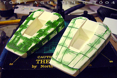
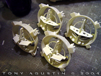
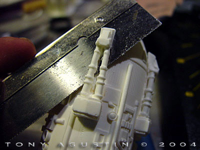
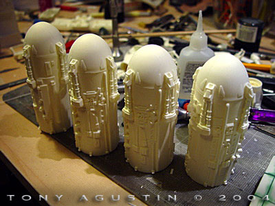
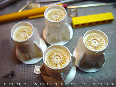
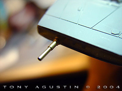
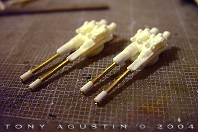
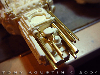
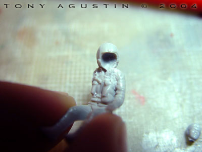
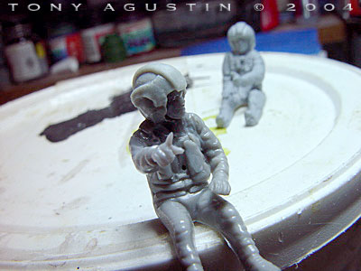
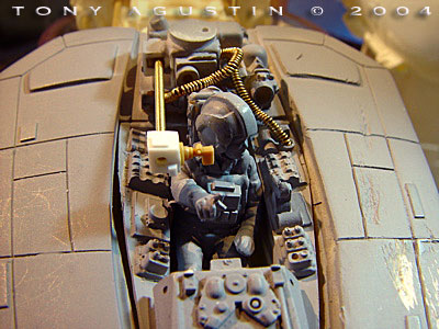
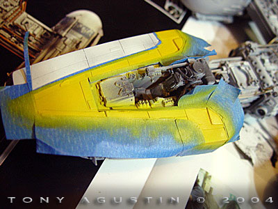
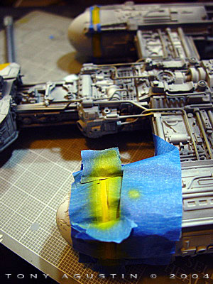
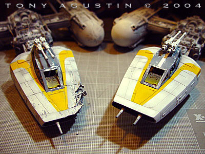
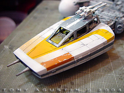
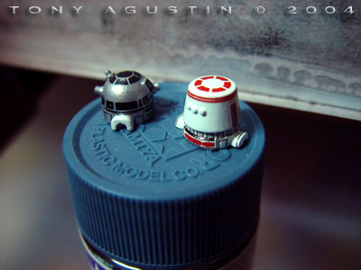
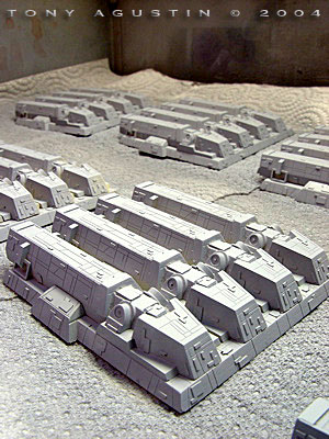
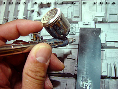
All in all I thought this was a beautiful kit with plenty of detail thru-out, but I did find one glaring detail problem that I felt really needed to be corrected. That problem was the width of the panel lines on the surfaces of the forward fuselages. On my copies they were much too heavy and looked very distracting. In comparison to the Y-Wing references I had, these panel lines had to be done in a much finer width. I normally like refining and/or adding extra detail to the kits I build and these Y-Wings were no exception. Smaller detail parts such as the weapons systems and the areas in and around the main engines needed to be cleaned up, re-detailed, partially modified or in some cases replaced. I found I would also need additional brass tubing and rod to supplement the brass and aluminum tubes and rods already provided in the kit. Display Ideas Before I could start the construction of the Y-Wing kits, I first needed to work out how to display the pair of Y-Wings some sort of dramatic way. I had made a Death Star Turbolaser Tower/X-Wing diorama the year before and got loads of positive compliments for the work I did on that. The ideas for that Turbolaser diorama came really fast and easy, but this Y-Wing project was a tough one. The ideas didn’t come to me as easily, and I really wanted to design a cool base for it. Years ago a prop company called ICONS put out a very expensive X-Wing replica that was mounted on a large square base made of Deathstar surface tiles. I thought that was such a cool way to display the ‘X-Wing’. It was simple and worked. I knew I wanted to incorporate that ICONS base-design with a few ideas of my own incorporated into it. I began to make very small sketches of what the base would look like along with a pair of Y-Wings that would be mounted onto it. The base needed to look slightly abstract because the surface tiles that I was going to make weren’t going to be in scale to the Y-Wings whatsoever. The problem of mounting both fighters to the base had to be worked out too. Thick acrylic rod would would have to suffice. Y-Wing ModificationsThe first thing to do was to fix up those those panel lines. Squadron Green Putty was used to fill them in with a small hobby putty knife. Once the panel lines were filled, I let both of the forward fuselages sit on a shelf for a week till the putty was completely cured. But in the meantime while waiting for the putty to cure I worked on the other smaller Y-Wing sub assemblies. Weapons Small diameter pieces of brass tubing were telescoped used to replace the forward laser cannons and the barrels of the topside ion cannon. In reality the topside guns are really slightly smaller on the actual filming miniatures but I felt the kit supplied ones were adequate enough to work with. I didn’t mind them. Engines Each of the main engines near the forward domes each had four ribbed, pipe-like details that were clogged with resin. They looked wrong and they needed to be cut-away for clean-up. They were liberated of excess resin and re-installed with short sections of styrene ‘T’ beam. The clean-up was done with a Dremel fitted with a very small grinding bit and polished up with a few jewelers files and an exacto knife. This tedious handiwork needed to be done 16 times for the two pairs of engine nacelles. That operation was a real patience tester. I didn’t like the the ends of the engine exhausts so I routed them out and inserted some spare resin vent detail copies from a WW2 German tank kit. The pieces I used don’t look a thing like the actual Y-Wing exhausts, but I thought they looked way better. At the extreme ends of the exhausts, the steering vector vanes were sharpened up to look thinner than they actually were. The large oversized rings tying the vertical and horizontal vanes together were replaced with thin strip styrene, gently bended to shape around a tank wheel of the perfect circumference. In one of the Joe Johnston sketches in the ‘Star Wars Sketchbook’ there was a long and short vectored Y-Wing in two separate drawings. I made one of my Y-Wing’s have longer vectors (‘T’ bars) than the other to differentiate them from one another. In the end the way the Y-Wings are mounted, you can’t really tell that one is about an inch longer than the other. Scribing Panel Lines Once the putty on the fuselages were completely cured, I filed and wet sanded the puttied areas till they were smooth. I then primed the surfaces with a gray sandable primer to look for surface flaws. If there were any flaws, I could wet sand them with fine grade sandpaper and re spray primer till I had a nice smooth surface. I use an exacto knife blade ground down to a ‘V’ shaped wedge. I made this scriber specifically for making panel lines. I used both a small stainless steel straight edge and a flexible curve as a guide for the scriber. Battle DamageI wanted the lead Y-Wing to be damaged in the front left quarter section. It needed to look like it was hit by floating debris from ‘unlucky’ rebel ships destroyed during their own ‘exhaust port’ runs, or maybe even from an energy bolt graze off of a trench mounted Turbolaser Tower. The Y-Wing had to be a ‘tough’ little fighter that could take the best the Empire could throw at it, yet still manage to fly at it’s top speed. To replicate the inner and outer structures of a damaged front quarter panel, I took a razor saw and sawed off a nice rectangular chunk of resin out of the front left corner of the nose section. Thin styrene sheet and a little epoxy putty replicated the bent armor panels. Small parts scavenged from 1/35 armor kits were used to detail the breached inner hull. A Dremel with a cutting bit was used to grind away at the areas to simulate shrapnel torn edges and surface scrapes. Cockpit I didn’t hyper-detail the cockpits, so the detailing inside them would be done very simply. I just added a few interesting looking scrap resin pieces from older projects. Air hoses were simulated by coiling up brass wire around a small diameter drill bit. Only the areas that would easily be visible from outside the canopy frame would be detailed. Tubing I used a lot of reference from the ‘Star Wars Chronicles’ book to help with installing the brass and aluminum tubing. Both Y-Wings would have identical tubing configurations in most areas but ‘artistic license’ was used to make the some tubing configurations unique to each Y-Wing. I used up most of the kit supplied brass rods and needed to get more at the local hardware store. Luckily this hardware store had a railroad section where I could get brass structural shapes. I also used some styrene tubing in a few areas where it didn’t need the brassy metal look. Holes were drilled out with a pin vice and the bent brass rod ends secured with CA. Pilots and Droids Of the two Y-Wing kits I had obtained, only one kit came with a pilot. According to SMT the other pilot wasn’t included due to problems with the fit of the figure in the cockpit area. In my spares box(s) I found a seated 1/48 pilot that would make a perfect Rebel Pilot replacement. It would need to have some surgery on it to get it to look like a pilot from the Alliance. The new pilot had a full face mask with hose, so I ground out the mask and hose area and hollowed out the helmet area where the face was with a Dremel. It looked like the invisible man. I filled the void in the helmet with the face of ground crew member from some Hasegawa Ground crew set I had laying about. Epoxy putty was used to transform the helmet. Sheet styrene was used to make the chest monitor. For the pilot that came with the other kit, I didn’t have to do too much to it but do some clean-up around the helmet areas and remove seams. The R5/R2 droids that came with the kit were kind of bad. They had a very weird surface not unlike the surface on styrofoam. Very pebbly. I wet sanded the details off of both the droid pieces till they were smooth. I left the square ‘eye’ area on the R2 unit and sharpened it up with a single edge razor. I found some small parts to simulate the protruding holographic projectors and whatnots on the R2 unit dome. I used chopped styrene rod for the R5’s eyes. Painting and Weathering My favorite primer is called Plasticote Sandable Primer. It’s in a spray can and could be found in white, gray, ruddy brown and black. I discovered these primers in the automotive section at Walmart and they are great stuff, just like Floquil primer but less expensive. You can either use it as is as a spray or spray it out into a small cup to thin it for use in an airbrush. Both Y-Wings/droids/figure were primed with gray sandable Plasticote. For the the painting of the Y-Wing fuselages I used a technique called pre-shading that I had just recently learned about from a local club member. It’s a technique of accentuating the weathering of panels, panel lines or other areas of a model in a subtle way. I airbrushed flat black primer into all the panel lines and areas on the ship that looked like it would get dirty. There was no need to get too subtle with the airbrushing here. Next up was an airbrush overspray of flat white primer to tone down the contrast. It worked really well if the primer is thinned. Rather then use the kit supplied decals, I opted to paint the yellow and light blue gray hull markings on. All large markings and off color panels were masked off with tape and airbrushed on. The cockpit interiors were simply airbrushed with a very thin flat black primer so as to settle in all the deep details. Nothing fancy there. For the paint chipping effects I went in with an old dull exacto knife and lightly scraped thru the layers of paint making sure I don’t scrape too hard to reveal the resin surface. Further weathering was done with a few washes of acrylic grimy black, rust and straight flat black into all the nooks and cranny’s. Some areas needed to be dirtied up a bit so I used a really thinned down grimy black thru the airbrush. The pilots were hand painted with Freakflex acrylic colors. The Droids were masked and painted with an airbrush using acrylic colors and flat metallics. |
|
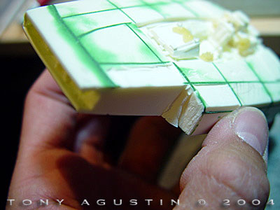
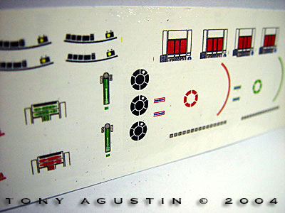
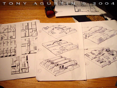
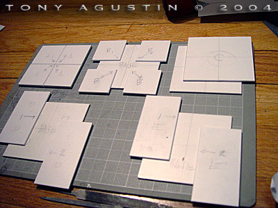
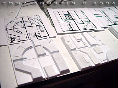
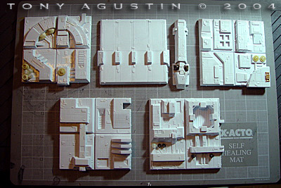
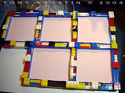
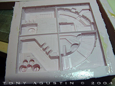
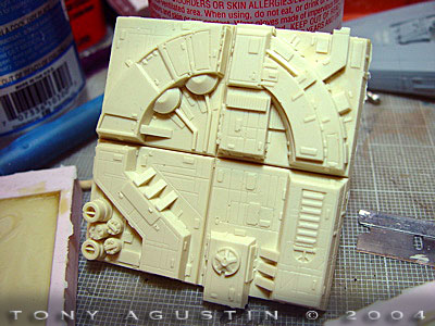
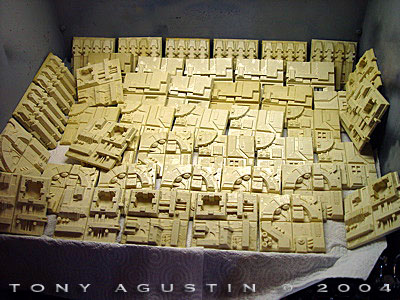
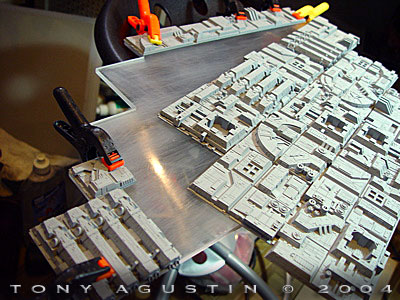
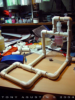
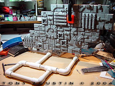
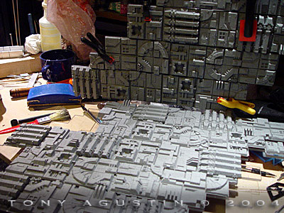
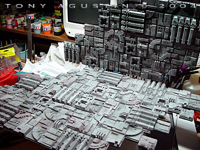
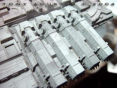
Decals Droid and pilot helmet decals needed to be made, so to make the decals I scanned leftover pieces of Finemolds X-Wing decal sheet which still had extra R5 and R2 markings from my previous Turbolaser project. Additional helmet graphics were made from references found off internet searches. I tweaked the scanned decal images and internet .jpgs in Photoshop, and printed them onto decal paper with a very high resolution to preserve the sharpness. Future floor polish was airbrushed or hand brushed onto the appropriate areas for a nice glossy undersurface for the decals to lay tight. Additional railroad dry transfers were cut to size and used to add the little rectangular details on the hulls. For the final finish both Y-Wings were then airbrushed with Gunze Sangyo clear flat. The Base: Making Deathstar Surface Tiles I started by locating my 26 year old copy of ‘The Star Wars Sketchbook’ by Joe Johnston. It’s dog-eared and almost falling apart and is among my favorite vehicle design books. As a 14 year old back then I voraciously copied every single drawing in that book in pen and pencil. In that book were fantastic designs of ships and of Deathstar surface tiles. Five of them to be precise. Joe Johnstons drawings would be used as the guide for my version of the Deathstar surface. When looking through reference photos of the actual Deathstar surface, the screen-used surface tiles were very crude looking. They had to be built very quickly since they were only meant to be seen as just a fleeting glance on film. I wanted my versions to be more detailed even when looking at them up close with the naked eye. So, five different tile masters needed to be made and a silicon mold taken from them. Multiple resin copies would then be pulled from those molds. Making Tile Masters Each tile would be a 3”x3” square so I scanned the drawings from the book and printed them out to those dimensions. They would be used as the guides to cutting out the shapes from thick styrene sheet. These tiles were made concurrently in between the Y-Wing construction. I used a Dremel scroll saw to help me cut thru the thick styrene sheet. Each structural shape that was cut out was then filed and sanded till the edges were square and the surfaces were smooth. Panel lines were scribed onto each tile and small .010 plates from strip styrene were added randomly. Each tile could be cut up into either four separate 1”x1” tiles or a pair of 1”x3” tiles for an almost never ending configuration. The most difficult tile master I had to make was the one I called the ‘piano keys’ tile. This was the one with four long sections laid side by side that looked like ‘piano keys’. Instead of making 4 separate ‘piano keys’ I made just one separate ‘key’. It took almost a month to complete these masters, but once they were done they were cleaned and prepped for the silicon rubber stage. The tiles were glued onto a heavy sheet of styrene and then walled up with LEGO pieces to contain the rubber. Silicon rubber was mixed with it’s catalyzer with an electric drill fitted with a paint mixer. An old paint brush was used to paint the newly mixed rubber onto the masters to make sure every area was covered. The rest of the silicon rubber was then poured in and the tiles left to cure for 24 hours over a room heater. Making Resin Copies Once the molds were cured it was time to do what I hate the most. Making resin parts. I had emptied the stock of Alumilite Resin from my local hobby shop the week before and now it was time to experiment on how much resin could be mixed for each part so as to keep waste way down. There definitely is a learning curve when making parts and I did my best to eliminate bubbles by prodding at the molds with a rounded wooden skewer. Clean up of the tiles was not fun. I found that some of my cast tiles were not a perfect 3” x 3” and I really had to put my Micromark disk sander to heavy use. Resin dust was EVERYWHERE. In the end 80 good tiles were successfully made along with 52 individual ‘piano key’ pieces. All in all 132 parts were made for two projects and that’s not counting the dozens of poor casts that could not be used. Each tile was primed with gray sandable primer in my spray booth and placed practically anywhere I had free space so they could dry. A Support Frame I designed a support out of 1” PVC pipe with connectors. It would be constructed to form a right angle. A floor of tiles would be attached to the PVC support as well as a back wall with screws. The Y-Wings would be mounted on two acrylic rods supported by the thick PVC connectors. Rows of tiles would be glued onto large plastic ‘For Sale’ signs and in turn glued and clamped onto thick acrylic sheets. The edges of the acrylic sheets would then be dressed up with chopped styrene structural shapes to match the tile detail. The PVC supports needed to be disguised too, so the areas that showed under the acrylic sheeting were dressed up with leftover resin parts from past and ongoing projects. Painting the Base The PVC support and acrylic sheet edges were painted with Plasticote Ruddy Brown Primer. I liked the shade of the gray primer for the tiles and left them that color. At first I was going to leave the tiles with that shade of gray pimer and call it a day, but I decided that Pre-Shading needed to be performed here to make the tiles look more interesting. I used a right angled plastic mask and airbrushed thinned down black, white and ruddy brown all over the tile surface making sure that panels were different colors and looked accentuated. This was done very quickly and didn’t need to be too perfect. 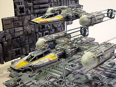 An overspray of the gray primer toned down the whole surface and blended every thing together. An overspray of the gray primer toned down the whole surface and blended every thing together.
Mounting the Y-Wings I drilled a pair of 1/4” holes thru the tiles/sign and acrylic sheet and into the PVC support connector to accept a thick 1/4” acrylic rod which would hold each Y-Wing up. 1/4” holes were drilled into the bottom of each Y-Wing and dry fit onto the acrylic rods. The heights of the ships were adjusted by trimming the length of the rods. And in the end .... This entire project took just under 5 months to complete. 'The Last Mission Of Gold Flight' Y-Wing project won 4 First place awards at the Northern Illinois Modelers Open 2004 and a Silver at Wonderfest 2004. |
![]()
This page copyright © 2005 Starship Modeler™. First posted on 26 January 2005.
![[Click to enlarge]](ta_gold/DSC07374.jpg)
![[Click to enlarge]](ta_gold/DSC07375.jpg)
![[Click to enlarge]](ta_gold/DSC07378.jpg)
![[Click to enlarge]](ta_gold/DSC07379.jpg)
![[Click to enlarge]](ta_gold/DSC07380.jpg)
![[Click to enlarge]](ta_gold/DSC07381.jpg)
![[Click to enlarge]](ta_gold/DSC07383.jpg)
![[Click to enlarge]](ta_gold/DSC07384.jpg)