
|
By Steven Jochums - images & text © 2012
|
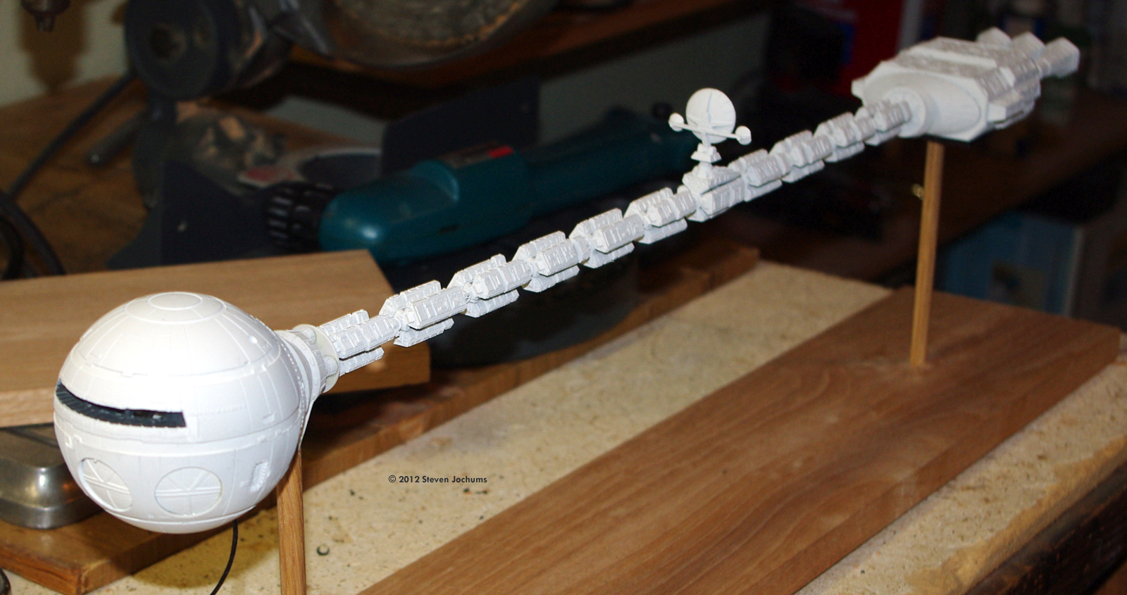
At last, I finally found a model I had wanted to build since seeing 2001: A Space Odyssey in 1968. Starship Modeler was a tremendous asset in this endeavor. Not only was it the means to acquire a copy of this kit, but the build reviews of Karl Dodenhoff and Brian Thewlis proved to be quite valuable in determining my own strategy in building and detailing the model. Like both Brian and Karl, I was going to build a full interior - both the flight deck and the Pod Bay. |
![[Please click to enlarge]](sj_discovery-48.jpg)
|
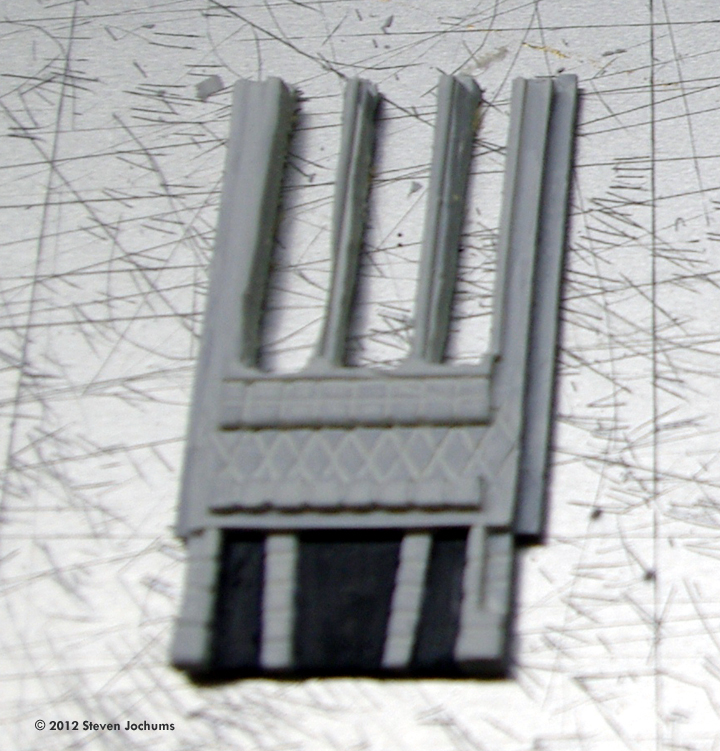
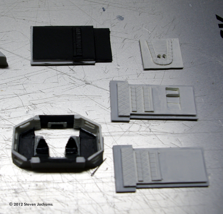
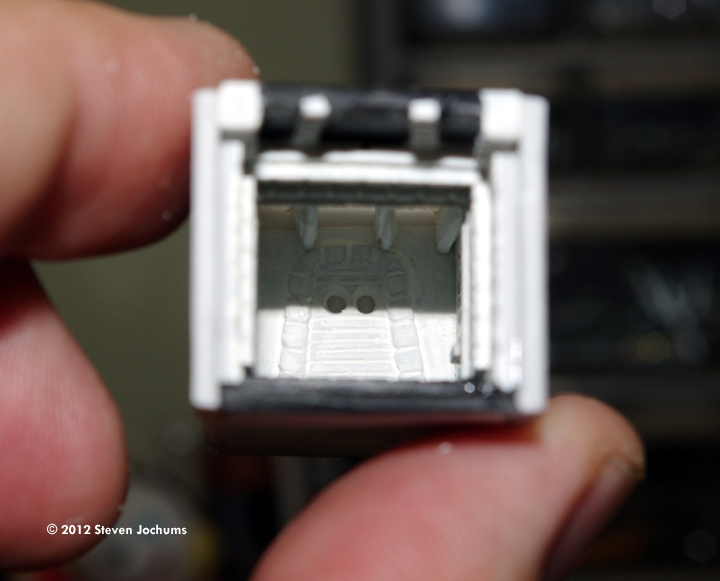
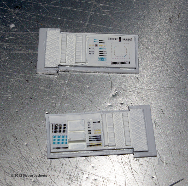
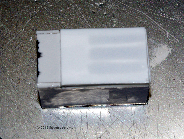
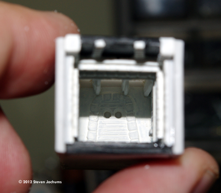
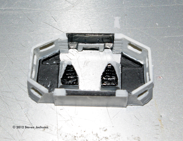
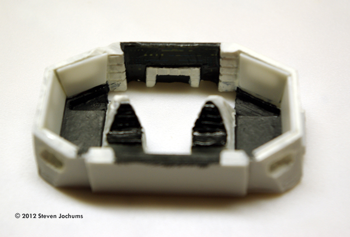
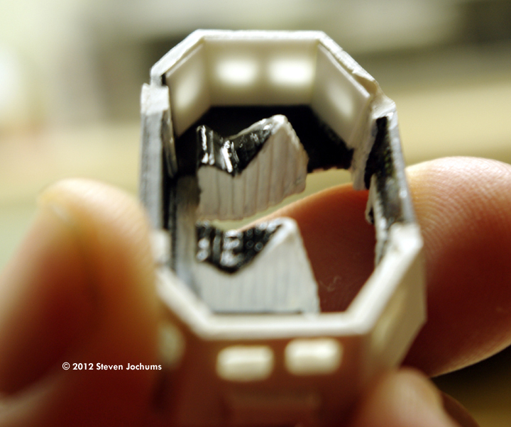
Image: Opening up panels for lighting. Image: Base colors for the flight deck. Image: Lower forward section of the flight deck, painted and decalled. Image: Attaching the white styrene for the overhead lighting. Image: Rear door portholes painted yellow. Image: Side wall decals. Image: Assembled anteroom - outside ... Image: ... and inside. Image: The translucent panels ringing the flight deck were drilled open ... Image: ... then covered with white styrene. Image: Let there be light!
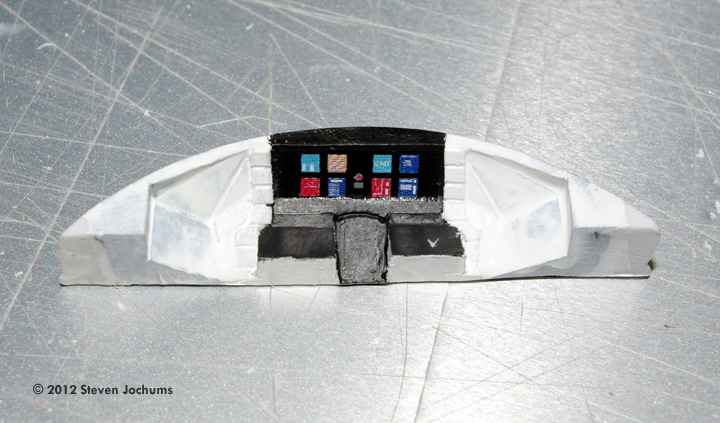
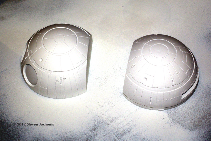
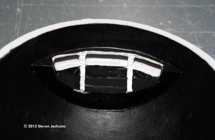
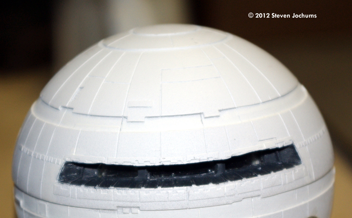
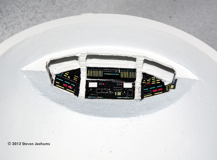
^ Crewman. Image: Outside of the Command hull is painted Primer White... Image: ... while the inside gets a coat of black before more white. Image: The windiow well was painted flat black. Image: Detail painting and decals. Image: Console.
^ Everything in place. Image: Opening up the lighting panels in the Pod Bay.
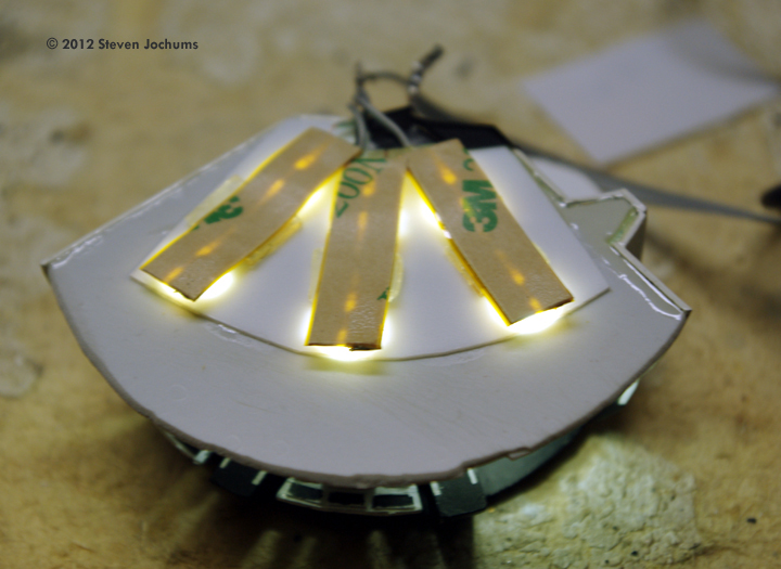
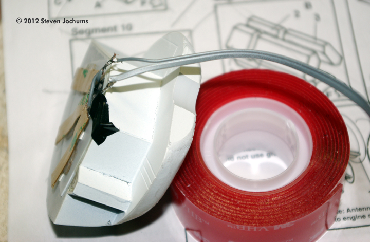
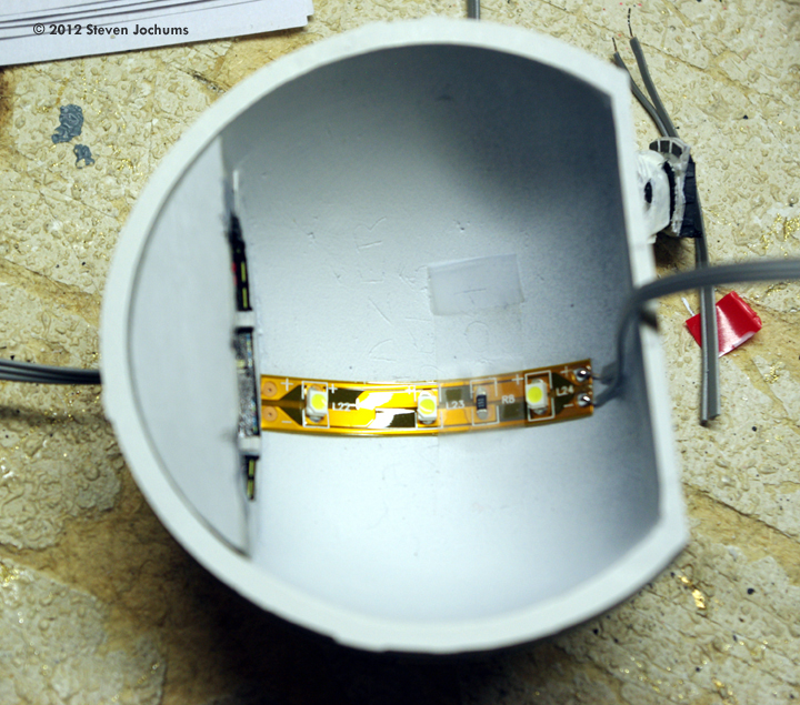
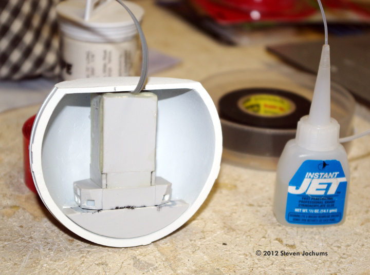
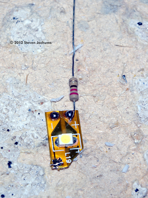
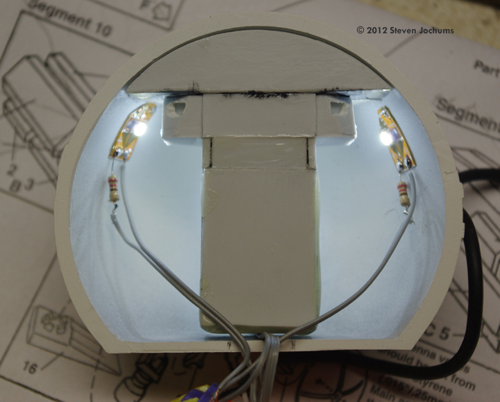
^ Pod Bay Image: Pod Bay ceiling installed Image: LED strip, shortened. Image: Each LED strip small was held in position by sections of double-sided gel tape. Image: In place and lit.
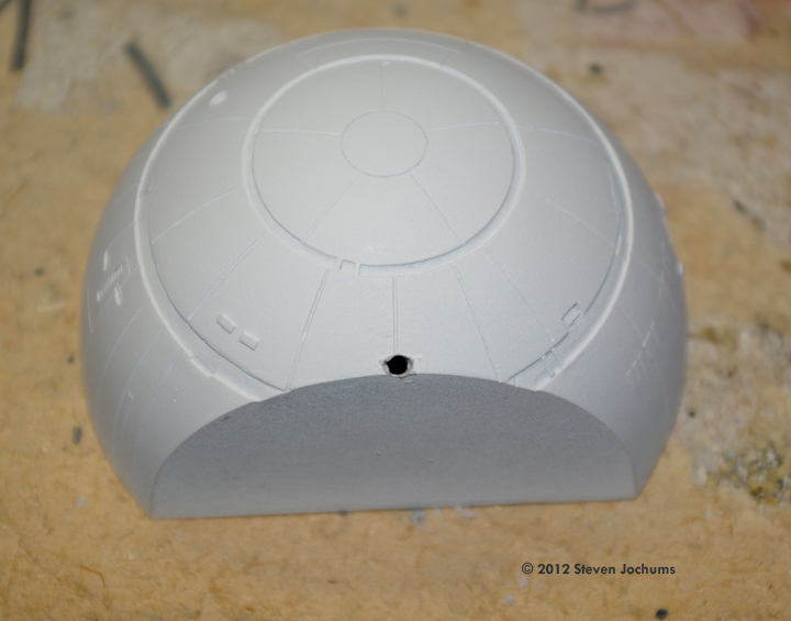
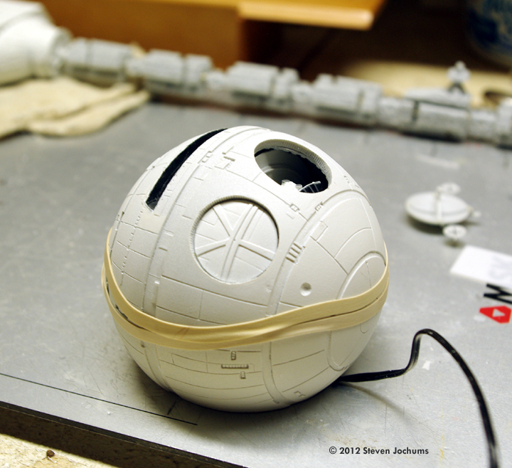
^ This photo was taken when the right-side Pod came loose due to handling. It was subsequently returned to proper position. Image: Hole in the CM for the wire to exit. Image: Trough for wires behind the Pod Bay. Image: Flight deck lighting. Image: Flight deck in place. Image: Side lamps were made from the remaining single LED strips... Image: ... and placed in the CM. Image: Pod bay installed.
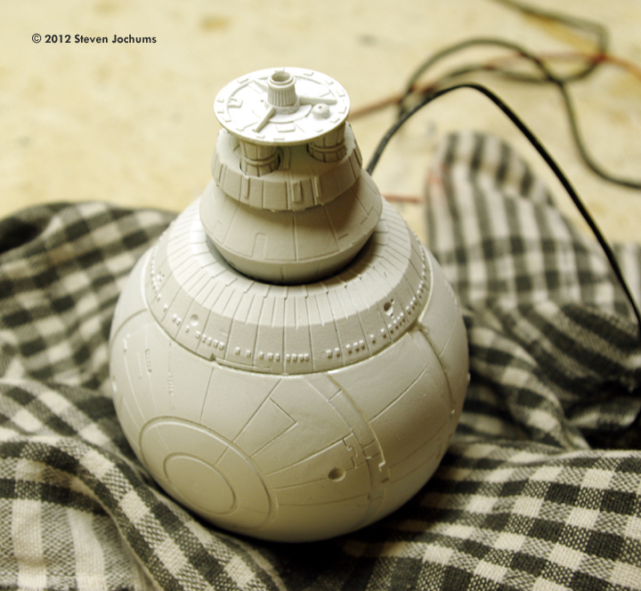
^ Lighting/wiring check. Image: CM closed up. Image: Command Module/Spine Adapter Unit assembled and drilled out to accept the spine rod. Image: Completed forward section.
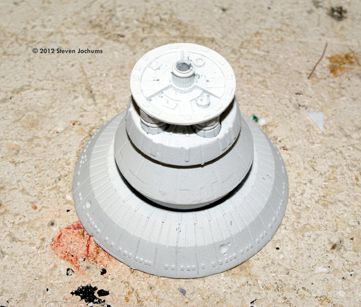
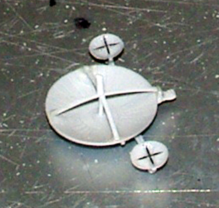
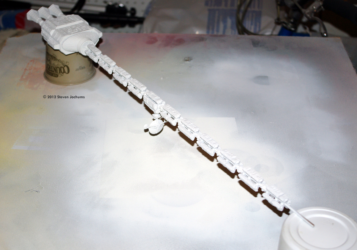
^ Completed Reactor Unit, with spine. Image: Assembly jigs for spine segment work. Image: Spine parts, cleaned up and separated. Image: Built up Spine modules. Note the steel pins between subsections. Image: Antenna array, showing guide hornes and PE pieces.
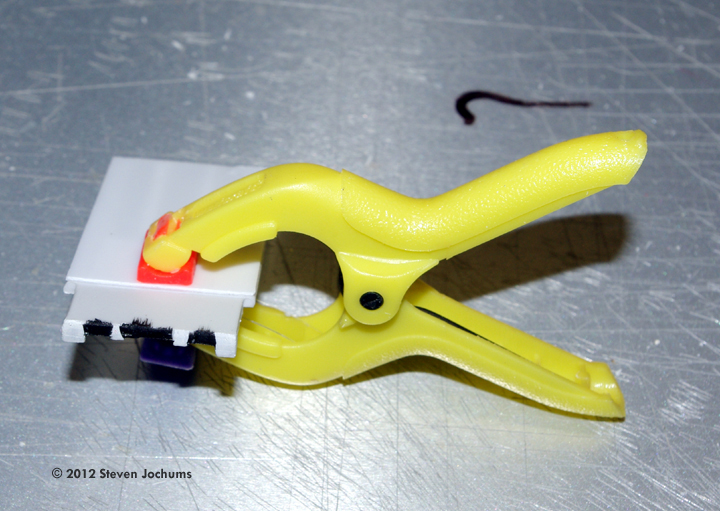
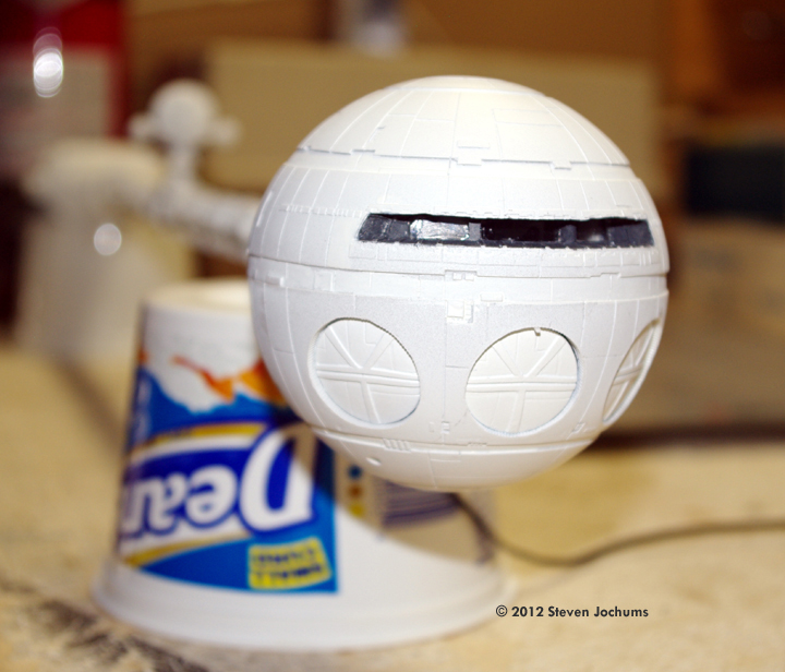
^ Completed Antenna Complex. Image: RU-Spine assembly, painted Image: Central Pod Bay door, closed. The small tab that keeps it in place is only apparent because of the shadow caused by the camera flash.
^ ... and open. Image: Display stand Image: Spindles painted. Image: Pin washes bring out surface detail.
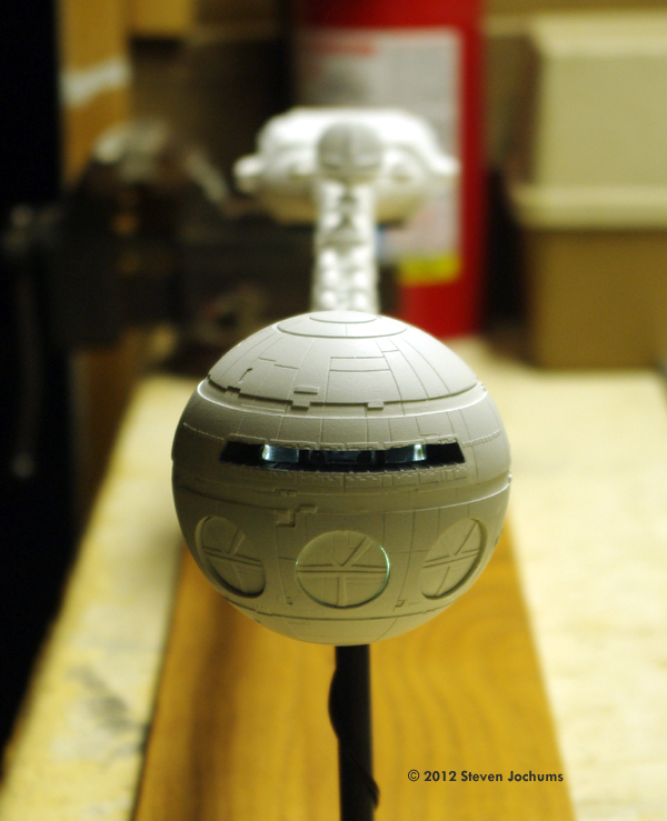
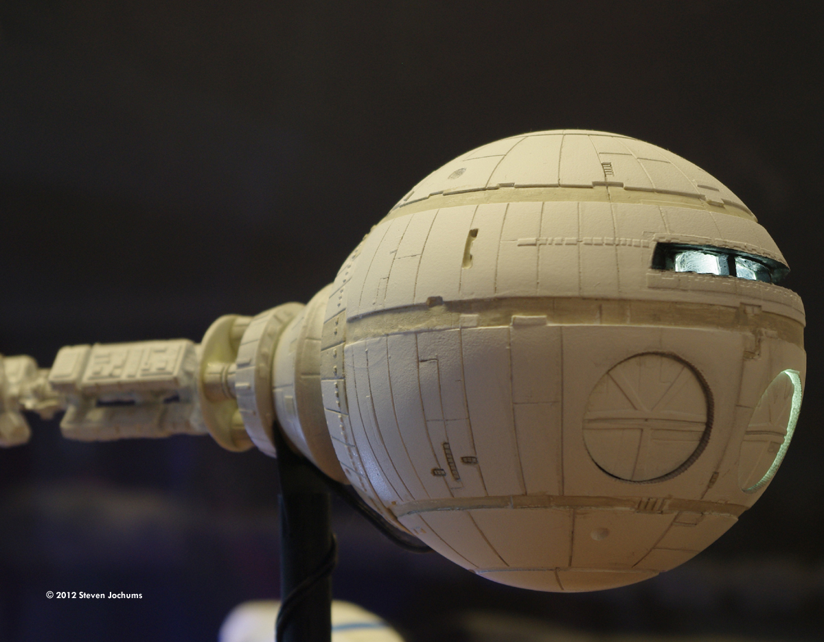
^ View through the CM windows. |
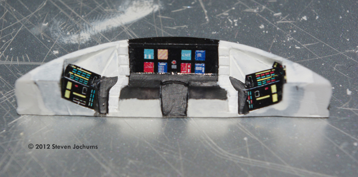
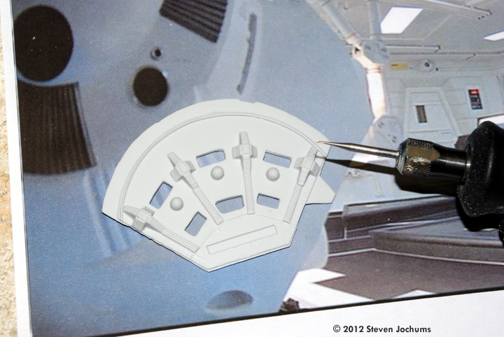
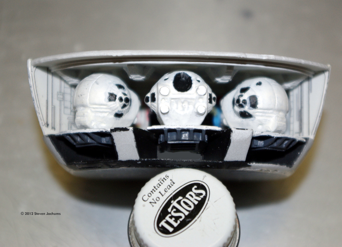
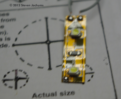
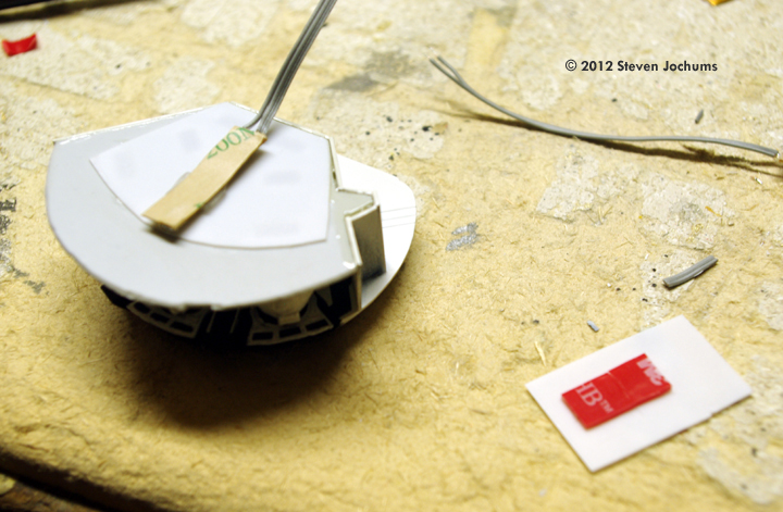
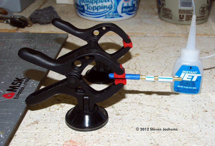
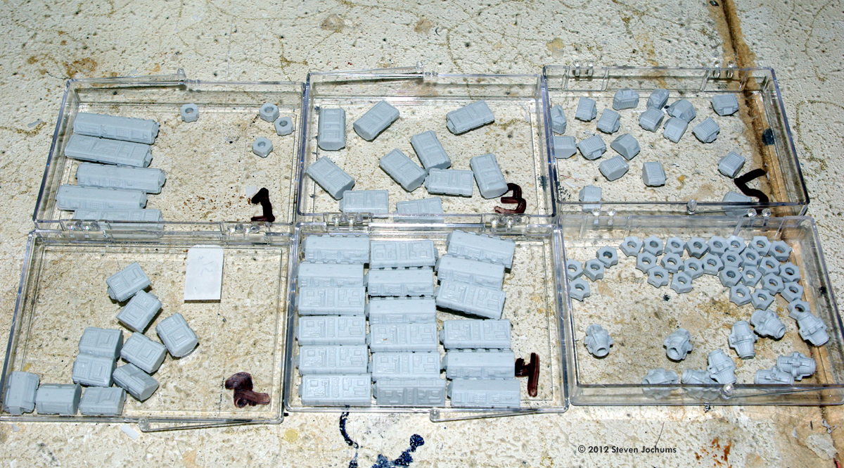
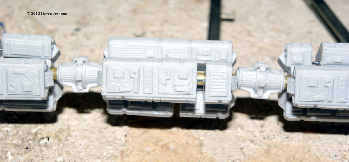
However, that's where the similarities in the final build stop, as I did not wish to extend the Pod Platform outside the hull, so the Pod Bay Door could be placed back into the "closed position," allowing both levels of display, and I also wanted to do a the flight deck lighting more in concert with the look of the movie flight deck set. Flight Deck / Ante-Room Construction The build of the flight deck was as the Stargazer manual described, except that I wanted to do the "ante-room" lighting through a translucent panel, as seen in the film, as well as light the perimeter of the flight deck through the translucent panels also seen in the film. This required removing the plastic from the ceiling panel between the long horizontal braces, and opening up the panels along the sides of the flight deck, using a Dremel and rat-tail file for finish work. The two windows on the rear door of the ante-room were also opened up so that light could come through. Using movie stills for reference, I found that the ante-room and flight deck carpet is black, so flat black was use on the floor sections. The walls were flat white, as a background for the instrument decals. The section of the roof panel which mates to the flight deck was also painted flat black, as this section merges with the black instrument panel decal on the upper surface of the flight deck. I also painted the rear walls to the flight deck flat black, rather than using the decals provided. The two flight deck seat supports are gloss white and the seat padding is gloss black. All of the "padded ribs" on the flight deck roof are gloss white as well. The lower forward section of the flight deck, which mounts into the upper hull hemisphere, was painted flat white as a background for the decals. A section of 0.20" thick white plastic sheet stock was cut to size for the opening of the ante-room roof, and glued into place. This is translucent media for the overhead lighting. The same material was used for the two small windows of the rear ante-room door. The rear door plastic was painted in clear yellow to set the proper lighting color. Then the decals were added to the side walls of the ante-room and forward control panel, so they could be set and dry fully before full assembly. The ante-room was assembled first. The floor, the side walls and the rear door panel were bound by rubber bands and glued. Once dry, the bands were removed. Next, it was time to look at the forward section of the flight deck. In the film, you can see translucent panels ringing the outer surface of the flight deck, between the rear walls and the forward panel. The detail of these panels exist on the part, but needed to be cleared of material by means of the Dremel. After finishing the openings with a rat-tail file, section of 0.010" white plastic were placed over the interior surfaces. This created the smooth interior wall finish, but allows the light from the openings to come through. Once completed, the forward section was fitted to the Ante-Room to create a single-unit assembly which would be fitted to the upper hull later. I used a "jump-suited" technician figure from another 1/144 scale model to replicate one of the Discovery crew checking the controls on the Ante-Room wall. After painting the figure for the appropriate blue suit color and facial and hair detail, he was secured to the Ante-Room floor. At the beginning of the build, the exterior of the Command Module hull sections were painted in Primer White. The interiors were done in Flat Black first, to act as a light block, and then in Primer White to set the interior main color. The "well" around the forward windows was hand-painted flat black, to match the look of the movie model. The control console decals were then added to the interior surfaces of the upper hull as specified. Once the decals had set, additional interior painting was done to bring the area in concert with the movie stills. The lower console section was also done in flat black - primer white as the upper hull was prior to placement of the decals. The 0.010" clear plastic front windows were then installed, using Testor's Clear Window Cement. Once cured, the lower console was located and glued into position. The upper hull was now ready to receive the flight deck assembly, once a lighting scheme was decided upon. Pod Bay I decided to work on the Pod Bay at this time, as the finished height of the Pod Bay would have an impact on the lighting system. The Pod Bay was fabricated directly along the lines provided in the Stargazer instruction manual, with one exception, I think. In my build, the ceiling of the Pod Bay was set onto the interior top edge of the Pod Bay walls instead of on top of them, so that there was no extra height above the walls. This would allow the placement of the ribbon LEDs to the ceiling after placement into the hull, without interfering with the flight deck assembly above. This required that the "ledge" around the perimeter of the ceiling, as well as the dimensions of the in-set on the right side, to be filed down. I used 0.010" white plastic as the translucent media for the Pod Bay ceiling. The openings in the ceiling had to be opened with the Dremel tool, then the part was painted alternately in Flat Black and Primer White. Once dry, the 0.010" white plastic was installed over the openings to become the translucent panels. The bay walls were traced from the wall decal onto 0.020 white sheet plastic, cut out and cut down into segments and set into position on the Pod Bay floor disk and allowed to completely cure. Then, the entire bay interior was painted Primer White. After drying, the decals were positioned. The wall and floor decals were far more problematic than I would have expected. Because they are so thin, it would have been better to place them prior to assembling the wall onto the bay floor, but we managed to get them in place anyway. After decal placement and drying, the interior was over-coated in Dullcoat to seal the surfaces. (Photo 20) The backside of the walls were then painted Flat Black for light-proofing through the plastic, then painted white to promote internal reflection. The three space suits were painted as seen in the movie and secured to the Pod Bay floor immediately behind the HAL 9000 console, in their "stowed" locations. Early on, I decided not to try to extend a pod platform outside the open Pod Bay Door, so that a way to reattach the door could be made. This way the model could be displayed open or closed. So, to facilitate the "open" phase of the look, the center Pod was fixed to its platform facing outward. The two other Pods faced inward, in their "stowed" positions. Then the Pod Bay ceiling with its translucent panel was installed onto the inside edges of the walls. Based on a visual examination of overall fit, it appeared that a 2-3 mm gap between the finished upper surface of the Pod Bay and the top edge of the lower hull would allow for the LED ribbon without touching the bottom of the Flight deck Assembly above. This is why the Pod Bay ceiling was placed inside the walls. The rest would be controlled from above. Interior Lighting for Discovery With the Pod bay assembly complete, it was time to address the bay lighting. I had already decided to use segments of the ParaGrafix E-Z-LED system to do the job. The segments normally have three LEDs each, with a single current-limiting diode for all three, and solder points at both ends for electrical attachment. But because of the spacing of the openings in the Pod Bay ceiling, only two LEDs actually "lined up" with the two forward-most openings. So I decided to use this layout, which required removing the third LED on each of three segments, and "shorting" the wiring traces at that end to complete the circuit on the segment. Then, each two-LED segment was held in position on top of the pod ceiling by small sections of 3M clear VHB double-sided gel tape. The three positive and negative lines were combined and insulated from each other to create a common connection point. A trial fit of the Pod Bay assembly into the lower Command Module (CM) hull indicated a very slight rise of the LEDs above the edge of the hull. This would require that the flight deck provide a slight degree of clearance when it was installed onto the Upper Hull. This meant that the bottom edge of the flight deck unit be placed as close to the edge of the opening for the forward console section on the upper CM hull as possible, without light leaks. More on this later. The Bay was removed from the Lower Hull and a location for wiring exit was determined. A small hole was made dead-center of the bottom of the circle of attachment between the Command Module and the CM/Spine Adapter Unit. For wiring clearance past the floor disk, a simple trough was sanded out with the Dremel sanding drum. A number of different locations were tried for lighting the Flight deck assembly, but the best results were going to come from a full E-Z-LED segment placed onto the inner surface of the CM upper hull above the Ante-Room ceiling, and LEDs placed on the inner surface near the sides of the flight deck, to illuminate the wall panels. Then the Flight Deck assembly was secured to the forward console area as intended, making sure that the bottom edge of the Flight Deck was as close to the bottom edge of the forward section opening as possible, to allow clearance for the Pod Bay lights. The side lamps were fabricated from the "removed" individual LEDs from two of the Pod Bay segments, each equipped with its own 220 Ohm current-dropping resistor. They were then located along side of the Flight Deck on the hull's inner surface. Again, all positive and negative leads were combined for common connection. A thin, flexible two-conductor lead wire was passed through the opening in the lower hull and brought up beyond the top of the hull. The Pod Bay assembly was then placed into the lower hull, checked for alignment and glued into place. Once set, the upper and lower halves were brought together, back edge to back edge, and the final electrical connections to the lead wire was made, soldered and insulated. After a check of all LEDs and a test fit, the halves were aligned and glued together. Once the CM glue had cured, it was time to do a "light leak check." I connected the lead wire to the power supply and turned off the workbench light. It was very easy to see where the seam between the upper and lower halves still did not close completely - even after sanding and testing of the halves prior to paint. The thin gap was filled with super-glue, allowed to cure completely, then painted flat black with grey and then Flat White to close the "wound." Thus the seam was closed. The Command Module/Spine Adapter Unit was fabricated next. Each part needed to be drilled out, to accept the Spine Rod during final assembly. Once each part was drilled using a small drill press, they were glued together to complete the assembly. (Photo 35) The system was "honed out" by using a section of rod with a slight burr on the edge, in order to open the long hole just enough to make assembly easier later on. Once a smooth fit to the rod was verified, the CM and CM/SAU were glued together to complete the forward section of the ship, (Photo 36) Reactor Unit & Spine Rod The Reactor Unit was built up in direct accord with the Stargazer instructions, except the hole for mounting the Spine rod was done to each section of the assembly first. Using a small drill press, the holes were drilled for the three Engine Bell Units first, then the central hole for the spine rod on the other end, using shims to maintain "flatness" of the Reactor Unit on the drill press floor. Then, Parts 22, 23 and 26 were all drilled out for the spine rod as well. The rod itself was a "composite" of a 36 inch long, 1/8" brass tube with a slightly smaller steel rod slid into it for reinforcement. Super glue was run into the joint between the two parts to lock them together. The rod was used for the alignment of the pre-drilled RU parts during assembly. The rod was first inserted into the central RU hole to check for perpendicularity. Once convinced that the hole was "true," the spine rod was inserted again, tapped into position to "seat" it and locked with super-glue. Part 22 was slid down the rod into position on the face of the RU and glued. Part 26 was done the same way. The engine bells and two Part 25's were located on the rear face of the RU, glued and allowed to cure. Spine Segments The Stargazer instructions for the assembly of the Spine and its constituent segments provides full guidance on the make-up of each of the eleven segments, in terms of which parts are used and their orientation. The Stargazer manual eludes to fabrication of these components on the spine rod itself. In the review of the kit by Brian Thewlis, the idea of using a "jig" to fabricate the segments off of the model caught my attention. But in order to make these, I needed to fix the final length of the Spine Rod, so that a section "off model" was available. The "final" length of the spine rod was determined by using a copy of the dimensional pattern from the manual, plotting off the distance for the eleven segments and adding the required 2 inches of insertion length to support the CM/SAU assembly. The rod was then cut to length and the end de-burred and cleaned. I first used the "cut section" of the spine rod to hone out the RU and CM/SAU assemblies as decribed previously. Then, I create two assembly jigs for spine segment work. The cut section was halved, and each half had one end wrapped with blue "painter's tape" to provide a "stop" for the assembly work and was then supported by a spring clamp. The internal segment support pieces (Parts 27 & 28) were then slipped onto the rod, with sections of plastic drinking straw cut to proper length and placed between the pieces on the rod as spacers. The spine parts were then cleaned, sorted and "binned" so that the assembly could be better organized, and part counts maintained and controlled. The "A" (Type 1) components are "full-length" and were always placed first, if they were part of the segment. The smaller component groups ("B" - Types 2 & 3, or "C" - Types 4 & 5) were connected and spaced by drilling a small diameter hole in the adjoining faces of each part and using a piece of steel "straight pin" inserted between them and locked with super-glue, to create a physically stable sub-assembly. These were then glued into position onto the support pieces in their appropriate locations. The result of the jig was like working with an engine stand, as you could rotate the assembly to locate each new component in turn. These segment assemblies require patience, as they must be solidly glued together in order to work with them, and even super-glue takes time to fully cure. Once completely dried, each segment was inspected for gaps between the central support pieces and the components. If found, the gaps were closed with additional glue and allowed to cure. |
|
As one end of each of the cut-sections of spine rod had a slight "burr" on it, it could be used as a "hone" to clear out the centers of each segment and each segment "coupler" part (Part 30), so that they could be slid easily down the spine rod into final position. This approach allowed the placement, spacing and alignment of all segments prior to locking them into position with super-glue. The construction of the Antenna Complex was tackled next. The Main Antenna's central vanes were cut by hand from 0.010" white plastic stock, bent to create a shallow curve and located onto the dish. Two small sections of plastic rod were added afterward - one inside between the vanes and the dish surface, and one outside to create the antenna horn extension. The central vanes for the two smaller dishes were yet another matter, I could not get cut plastic pieces to look the way I wanted them to, so I went to a local hobby store and after some discussions with staff to tell them what kind of "cross-shaped" article I was searching for, I came across a set of photo-etched metal parts for a ship model, which had small cross-shapes on it, They were the right size to fit inside the diameter of the small dishes! After assembly of the vanes, the Antenna Complex was placed on top of its center segment. Once completed, the entire RU-Spine assembly was supported and painted in Primer White, to match the rest of the model. Final Assembly The central Pod Bay door issue had still not been resolved. The trick was to provide a stable means to keep the door in position for the "closed: mode, and still be able to remove it fairly easily for the "open" mode. The solution came in the way of placing a section of self-adhesive, soft gel "foot" onto the inner surface of the door, so that the distance from the Pod and Platform to the edge of the opening would be set on insertion. A very small ribbon of plastic stock was added, so that it bent over the top edge of the door and extended about 1.5 mm away from the door. The result is both a "shim" to create the friction necessary to hold the door in place, and a "tab" to pull the door free to change to "open" display mode. As the tab is white and projects no more than a millimeter away from the door's edge, it does not to detract from the look of the model in "closed" mode. A model like this deserves a good display stand, so I decided to fabricate one from a solid Red Oak plank, drilled out to accept ˝" diameter Oak dowel rods. The rear dowel was capped with a rectangular section of black 1/8" thick ABS plastic to support the RU and the forward dowel was capped with a 0.030" thick plastic support, shaped to cradle the CM/SAU at the second segment and slotted to accommodate the lighting lead wire. The spindles were then painted Flat Black and the Oak plank was sanded smooth and rubbed with a Teak Oil finish. |
![[Please click to enlarge]](sj_discovery-51.jpg)
|
Detailing The surface details of the Spine segments and the Reactor Unit were brought out by using a wash of flat black acrylic enamel in acrylic thinner, at a ratio of about four or five "brush-loads" of flat black into a 0.5 oz. bottle of thinner. The same wash was used with a very thin brush to accent the seams of the CM and SAU components. I am still in the process of detailing and panel painting. Extensive use of movie still and comparisons to other builds will be used for reference, but it's a long winter coming, and I don't have to hurry. Conclusions I feel the results speak for themselves. As I said at the beginning, I have been looking for a long time to have a properly detailed model of the Discovery. To see it fundamentally completed and sitting on the display shelf is both satisfying and surrealistic all at the same time. Many thanks go to Stargazer for producing the kit and to Starship Modeler for providing access to it! |
Please note that the opinions expressed in this article are those of the reviewer.
Read other reader's reviews of this kit ![]() Submit your own review of this kit.
Submit your own review of this kit.
![]()
Go back up | 2001: Index | Starship Modeler Home | Site Map | Feedback
This page copyright © 2012 Starship Modeler™. First posted on 26 August 2012.
![[Please click to enlarge]](sj_discovery-12.jpg)
![[Please click to enlarge]](sj_discovery-18.jpg)
![[Please click to enlarge]](sj_discovery-20.jpg)
![[Please click to enlarge]](sj_discovery-25.jpg)
![[Please click to enlarge]](sj_discovery-33.jpg)
![[Please click to enlarge]](sj_discovery-37.jpg)
![[Please click to enlarge]](sj_discovery-42.jpg)
![[Please click to enlarge]](sj_discovery-45.jpg)
![[Please click to enlarge]](sj_discovery-50.jpg)