
|
The projects in this section are presented as step-by-step journals. Our intent is to delve deeper into the nuts and bolts of constructing and finishing a particular project while giving a sense of how long it takes. The subjects will range from simple kits to complex dioramas and everything in between. Authors will range in skill level, and include hobbyists and professionals. If you have a project you would like to share here, please drop us a line to discuss it. |
| BETTY from Alien: Resurrection |
|
Project type: Scratchbuild
by Alfred Wong - images & text © 2003 The project I will document here is the construction of the masters for the Betty from "Alien Resurrection". The kit will be produced by SMT. The scale is approximately 1/144. I started by gathering a lot of photos and the sole available plans -- thank's very much to all those who sent me their references! The plans, it seems, have many differences from the studio model. So, while I can use them for some of the basic proportions, most of the specific shapes of the major components are quite different. Building a master is a bit different than straight scratchbuilding, because it must be broken down into castable components. The build must be quite clean, and the parts must be strong and rigid. Back to Current On-LIne Build |
|
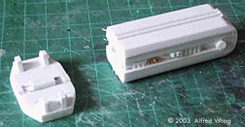
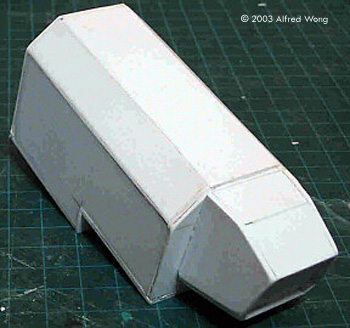
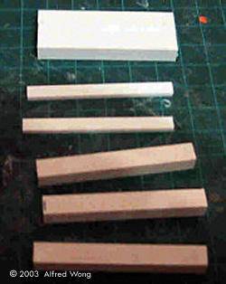
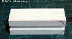
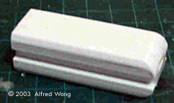
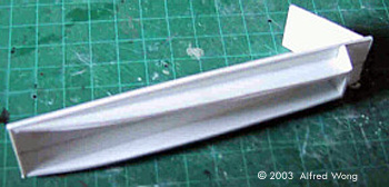
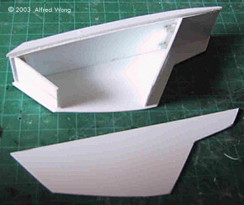
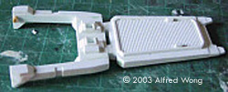
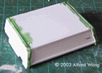
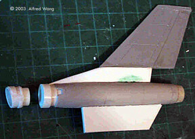
Image: Tail piece, front Image: Tail piece stiffened with plumber's (epoxy) putty Image: Sanding the mating edge to get a level surface Image: The completed main hull |
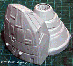
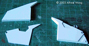
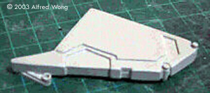
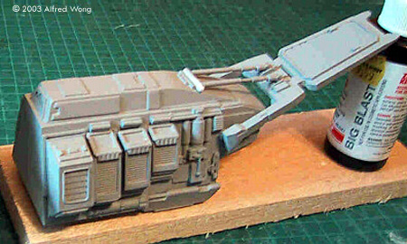
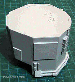
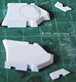
Day 1 Well, this isn't quite starting from the beginning, but pretty close. First of all, I had to figure out the basic shapes of the Betty's fuselage using photos and the available plans. I managed to break the fuselage into 4 main parts. The main body has 2 barn-like shapes, plus a piece for the nose and another for the back end. The shapes were made like boxes from 0.060 styrene (I haven't done the nose yet.) Since it's a master and needs to be very rigid and strong for molding and casting, the interiors were stuffed with bits of scrap balsa. Resin will be poured into the holes you see to fill up the remaining space. The joints were then filled and sanded. For smaller bits like the tail piece I stuffed plumber's putty into it to make it rigid. It's important to have a good joint for attachment to the body, so I sanded the base of the tail piece on a flat piece of 220 grit sandpaper. Then it was glued to the back of the body piece. |
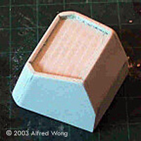
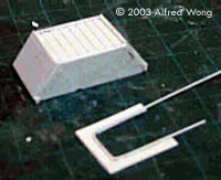
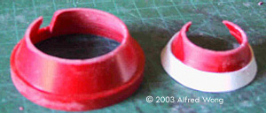
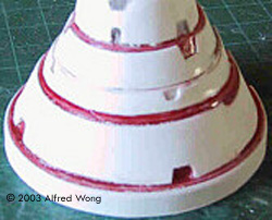
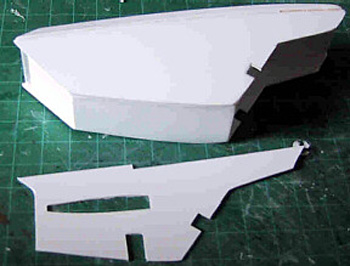
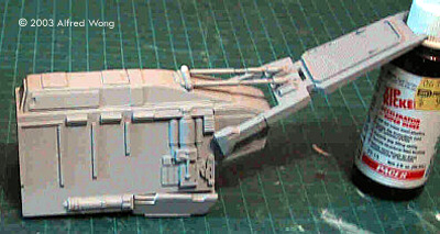
![[Click to enlarge]](aw_b/aw_b_tutorial07.jpg) ^ New rear fuselage with vents Image: Vent detail piece Image: New rear fuselage with vents in place Image: Scoring the cone Image: Useable cone sections Image: Segmented cone taking shape Image: Taping and tracing Image: The traced pattern was used to cut outscab-on detailing Image: The detailed cone |
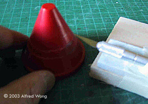
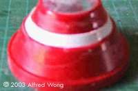
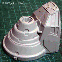
Day 2 I started the day making the vented detail pieces for the sides of the aft hull. These were simply pieces of trapezoidal styrene for sides and plain and Evergreen stock for the faces and detailing. At this point, I realized that I had goofed with the cross-sectional shape of the rear fuselage, so I had to make a new one. I removed the tailpiece from the old aft hull and attached it to the new one. I added locator pieces with styrene stock for the vent pieces. I only made them for one side; they will be cast in duplicates for the other. I also added some plate detailing with .020 styrene. I then decided to begin work on the difficult segmented cone mounted on top of the cockpit. Luckily, I had a cone from the spares box that was exactly the right diameter! I believe it originally came from a dollar store as the cap of a tube of pencil crayons. The hard part now was to separate it into segments. I taped my Xacto-knife to layers of scrap balsa to each of the heights of the segments and scored repeatedly around the cone. I was able to get a couple of usable segments with this method. I added one more using a strip of styrene, and the tip, using another scrap-box find. Using wide masking tape, I outlined each segment by wrapping around it, then transferred the pattern to a piece of .020 styrene. After cutting them out and cutting the various surface notches, I wrapped the styrene around the segments. |
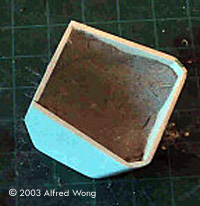
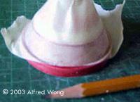
![[*(&^&^&(%##%!]](aw_b/aw_b_tutorial16.jpg) ^ Fiddly bits Image: Cockpit takes shape Image: Roughly positioned |
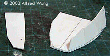
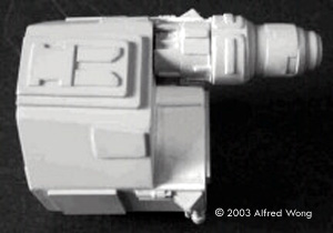
Day 3 Well, the entire modeling time today was spent fiddling with the troublesome cone piece. I also pieced together the main cockpit form. There was no real easy way to do it. I started with a piece for the floor and eyeballed the rest of the pieces as I built the shape around the floor piece, making adjustments along the way as needed. It's one of those trial & error type of process. The evening ended with the basic shape built and puttied. It will be sanded and detailed tomorrow. |
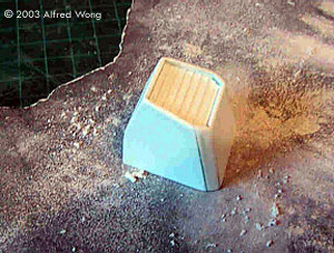
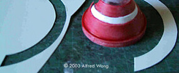
![[Detailed cockpit]](aw_b/aw_b_tutorial18.jpg) ^ Cockpit, detailed Image: Underneath Image: Final nose assembly Image: Nose assembly, underneath Image: The large bracket mountings were built from laminated sheet Image: End result |
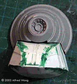
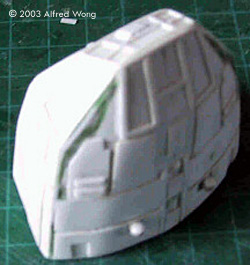
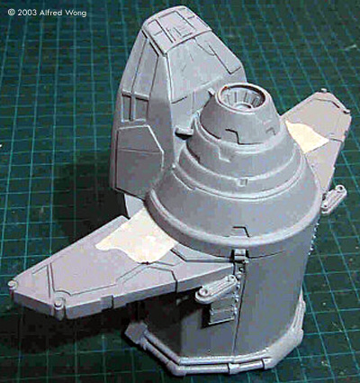
Day 4 I had half a day available for modeling today, but it was quite productive. I detailed the cockpit section with .020 and 0.10 styrene and finished up the cone section. I glued them together and filled the inside with plumbers' putty to make it strong for casting. I added the final details and shot it with Tamiya spray primer. What you see here is the final, finished master for the entire nose section. I began to work up the large bracket mountings which hold the lateral thrust pods. These were quite simple to make. I laminated 3 pieces of .060" styrene and faced the result with a piece of .030" that had cut-outs for the detailing. I then added the remaining detailing with Evergreen rod. I made one set, which can be cast again for the other side, the additional face details that distinguish front and back pieces can be made as separate components. |
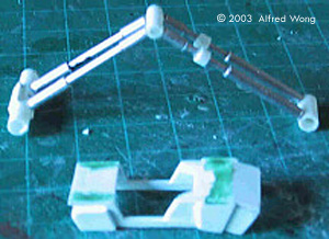
 ^ Completed thrust pod arm Image: Building blocks, made of laminated styrene Image: Glued and sanded Image: Edges beveled Image: Frame for the thrust pod Image: Pod takes shape Image: Pod and relief detail piece |
Day 5 5:30 am on a Saturday - what better time than to tackle the master for the arms that connect to the massive thrust pods? These were relatively easy to do. I laminated .25” square stock, with thinner stock for the channel in the middle. They were glued together and sanded, and the bevels on the edges were done by sanding them on a flat piece of 220 sandpaper. The middle channel was detailed with little greeblies, and the mounting plate was made with laminated .060" styrene and bits and pieces. That was a good warm up to get to the big pods themselves. A basic frame was made with .060" sheet, then boxed with more .060". The relief paneling was added with .030" and .020" sheet. The basic box for the pod master was then puttied. Sanding will commence tomorrow. |
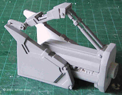
![[Click to enlarge]](aw_b/aw_b_tutorial31_lil.jpg) ^ Cockpit, detailed Image: Thrust pod, underneath Image: All the parts ... Image: ... put together |
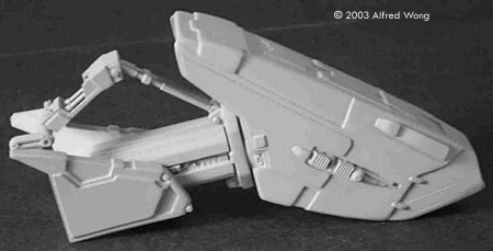
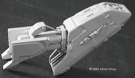
Day 6 Curling season started today, and Sunday is a busy coaching day for me, so a few hours this morning was all I had for modeling. I finished adding the relief panels and details for the thrust pod master, sanded it smooth and primed it gray. Here are a few pics showing the pod and the masters for the arm and brackets and how they all go together. The remaining details, such as the face details on the brackets and the hydraulics on the top and bottom of the arm will be made later. |
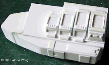
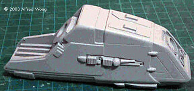
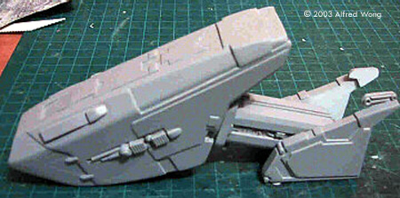
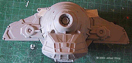
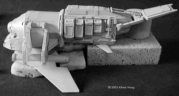
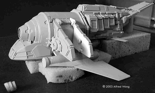
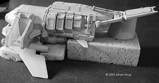
![[Click to enlarge]](aw_b/aw_b_tutorial35.jpg) ^ Aft hull and components Image: Flap Image: Exhaust under the tail Image: Finished aft hull Image: With the vents - looking good Image: Piping details Image: Nose and brackets Image: Another look |
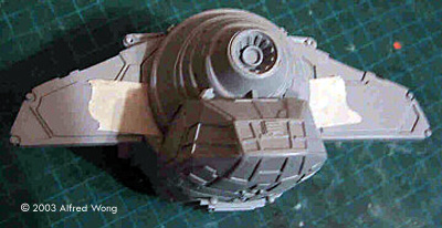
Day 7 I've been busy with storyboarding work on Mutant-X, but here's what I've been able to do since Sunday. I wanted to finish the aft hull, and built the remaining components. There is the big tail flap-like thing with its hydraulic arm and the box-like exhaust under the tail. The components were all built up with styrene and Evergreen stock. The Betty, with its heavy-machinery look, really lends itself to this kind of construction. The aft hull itself received some kit parts for details and was primed. There is no clear image of the detailing aft of the vents, so I just winged it, keeping the detailing with the spirit of the rest of the design. In one of the pictures at left you can see the finished aft hull with the other component positioned in place. The small fins that attach to the box-like exhaust will be separate parts. I also placed the vents onto the side so you can get an idea of the total assembly. I was happy with the way it turned out. I also finished the center hull with some detailing. Adequate info was available so I was able to make it as faithfully as I could to the original. The piping detail was somewhat tricky, and I had to be careful to fill in any undercuts that would spoil the mold. The last couple of pictures show the nose in position as well as the forward brackets - remember that the aft brackets use the same masters reproduced twice. At this point, I can count the components that remain to be mastered. They are:
So, things are going pretty well, and I hope to finish this up by the end of the week. |
|
^ Hydraulic actuators Image: Building up the hydraulics assemblies Image: Top set of hydraulics, in place Image: Bottom set, in place Image: Bracket detail pieces Image: Detail bits in place Image: Master for the jet engines and wings |
Day 8 Today was a most productive day! I got my storyboarding work out of the way relatively early by starting work at 5:00 am. I started my final parts list by doing the hydraulics for the arms. The hydraulics were made with aluminum and styrene tubing. The set of double hydraulic arms on the top will later be separated down the middle into two “V”s to make it easier to cast. The detail structure was made with styrene and Evergreen stock. The top hydraulics and the detail piece were primed and placed in position. The same was done with the single bottom hydraulic arm. Once the hydraulics were completed, I made the detail pieces for the front of the brackets. They were made with laminated .060" styrene with a bevel cut and sanded into the sides. Strips of .030" styrene were cut and notched to make the edge details. The circular detail was a matching half-wheel found in the spares box. A bit of sanding and shaping was all that was needed to make it a close match. To check fit, the finished parts were positioned on the brackets along with the nose and center hull with a little help from masking tape. Next up is the master for the jet engines and wings. As I suspected, a 1/48 scale F-16 tail fin was a perfect match for the wing. A fuel tank with some alterations was made to match the engine. I had to replace the root section of the F-16 fin with styrene because the kit part I had is the later, widened F-16 fin, where the Betty part needed the original, thinner F-16A fin root. I scribed new panel lines onto the fin and engine. So, the only things left to do now will be to construct a master for the paired engines under the hull, and another for the small brace for the rear brackets. Tomorrow! |
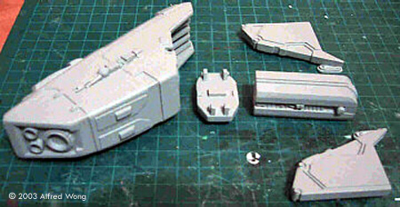
![[Click to enlarge]](aw_b/aw_b_Bettypartsall1.JPG) ^ The master parts Image: Engine master Image: Lateral engines assembly top Image: Lateral engines assembly bottom Image: Parts assembled - port side Image: Assembled, front/left Image: Assembled, left/rear |
Day 9 The last bits have been completed and the master is ready to be sent off for casting. |
![[[Battlestar Galactica models & more at the Starship Modeler Store]]](http://www.starshipmodeler.com/resource/bsg_ad_2.jpg) |
| Visit our sponsors! | Advertise with us |
![]()
This page copyright © 2003 Starship Modeler™. Last updated on 21 November 2003.
![[Click to enlarge]](aw_b/aw_b_tutorial1.jpg)
![[Hydraulic parts]](aw_b/aw_b_tutorial43.jpg)