
By Geert Van Den Eeckhaut - images & text © 2007
|
![[Please click to enlarge]](gd_vader_3kwartvoor.jpg) I am a scale modeler for many years, but didn't find much time the last years to practice it. So to get myself started again, I decided to do an "easy" thing in order to practice all the new techniques I had read about in the armor modeling magazines. |
|
Image: EL sheet Image: Testing.... Image: Cockpit parts, ready for paint Image: New, more detailed wing inserts Image: New detail 'box' in place Image: Inner wing detail Image: Old and new upper hatch Image: Fuselage rear detail to be salvaged Image: Assembling the panels Image: Old canopy used as a master for a new, clearer one Image: Lots of new detail added Image: Chin area - note the new blasters Image: Inner wing detail Image: More Image: Front view Image: All lit up Image: New stand |
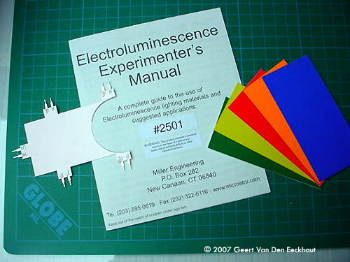
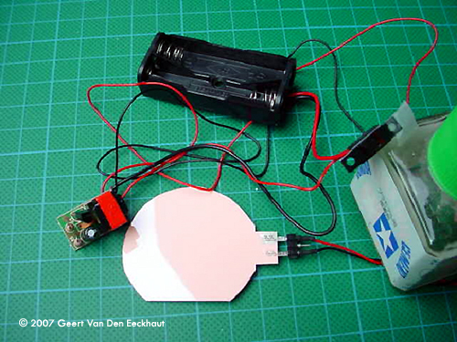
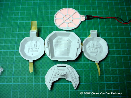
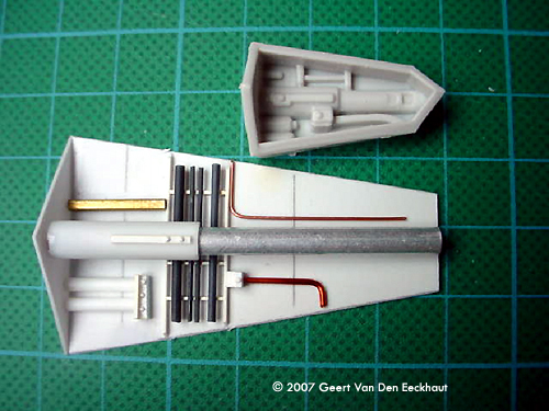
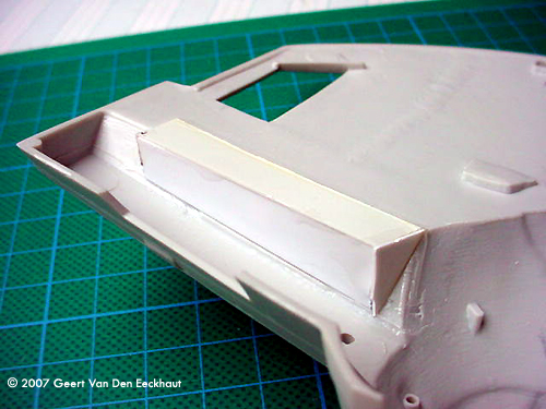
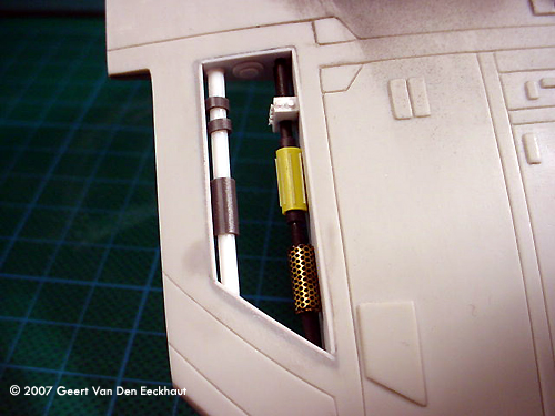
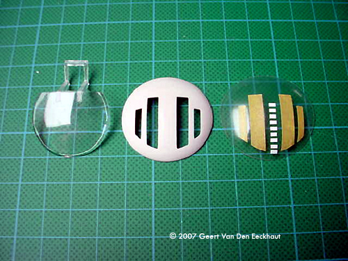
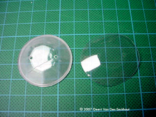
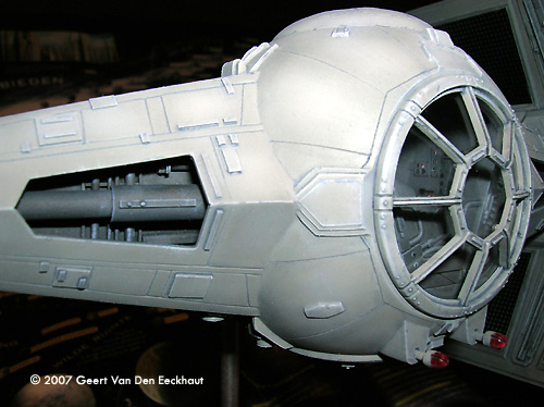
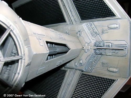
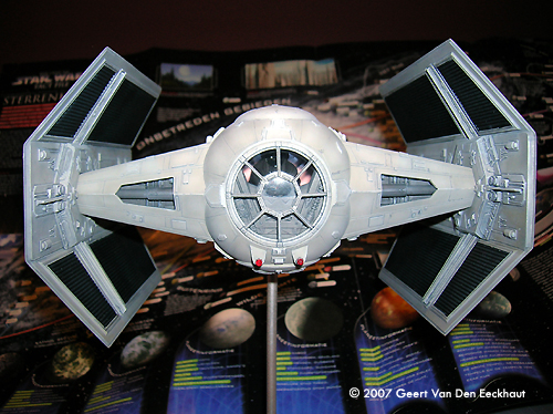
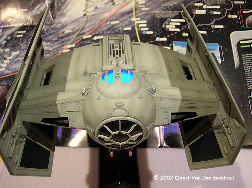
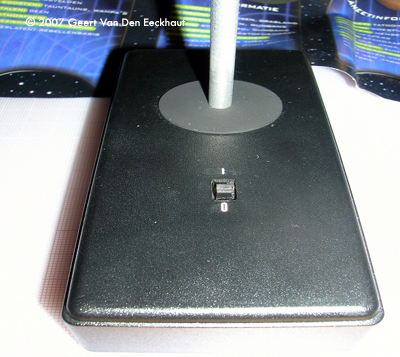
Why not a Star Wars kit? Something easy, I thought, I was looking for a simple kit to build without existing photo etching and lots of documentation. This was going to be a real modeling exercise, no update sets, just me and the kit. I took a quick look at the internet and stumbled in to Ward's article and got hooked. Since I was looking to build Darth Vader's Tie I used this article as a step by step guide and tried to do better (who am I?) There where Ward was not pleased with his choices I tried to come up with something more suitable from my point of view. Before I will loose myself in details I just want to say �thanks� to Ward for his complete and inspiring article. I am not rewriting his article, that would be a waste of time, after all he wrote some 15 pages! I'll take you on tour following the same sequence as the AMT ERTL plan. Here we go. Step 1: Darth Vader He's ugly, yes indeed! I gave him new eyes therefore I drilled his old eyes out from the inside of his head and put small balls in place, leaden balls, the kind fishermen use on their lines. I sawed off his hands and replaced them by a set with gloves on from Verlinden and finally I put a new strip on his helmet together with new bolts on his mask (mouth). I did not know how much one still could see once the cockpit was closed and illuminated --- and then I had the idea of putting electro luminescence sheet in it. Step 2 & 3: Cockpit I followed the kit instructions but included a backlight. The back side of the cockpit wall was sanded until I only got the ribs of what I called the aim. Then I took the electro luminescence sheet and cut it to shape. You have to be sure to include two connections on your shape to connect a little transformer to - you need a plus and a minus. The set, bought on the site of Micro-Mark, comes with a small switch, the transformer and a housing for two batteries. Once switched on, this sheet glows and gives off a bluish light. Other modelers use it to reproduce the bluish light of warp engines. I wanted Darth Vader to sit in his cockpit poorly lit like in the movie but just enough to catch a glimpse of the cockpit and this great character. Since I had already decided to put this model on a aluminium tube more or less in a flying situation, this tube served to lead my two wires down to my control box with the switch, transformer and batteries. Any way, don't use the landing gear included in the kit, ever saw a TIE skiing? Step 4: Fuselage Lower Half Ok, here started the troubles but luckily I learned from Ward's experience. I did throw away the six recessed boxes and started to make my own using the bad ones as a template. I wanted to be able to look into the recessed areas; I couldn't imagine looking upon a wall in that particular place. So for the four small ones, I made boxes with plastic card which I glued to the inner side of the lower and the upper fuselage copying the tubing present on the bad pieces. I did more or less the same thing for the two other boxes but these ones sit on the front of the fighter. So these had to be good, real good. In the picture you can see that I created a large surface with many details; it covers almost the whole length. Even an experienced eye can look into these holes and will see nothing else but hidden details of the tie fighter. I created it with tubing of different size and material and glued it in place. The last thing added in this step was the finished cockpit. Step 5: Hatch In one word �bad�. You'll have to glue a transparent part to a plastic one and than you have something that should look like a hatch. I used the plastic part as a mould for heat forming another one. If you do it correctly you will even have a very small recess around the four small windows. A couple of smaller details were added and finished. The windows were sealed with Tamiya masking tape for the future paint job. Step 6: Landing Gear Quick! Throw it away! Don't get spoiled by bad taste and move to step 7. I closed the holes provided for the landing gear with plastic roundels. You can make these easily with a punch & die set. |
|
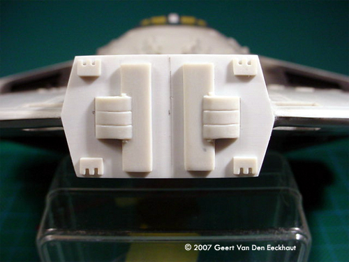
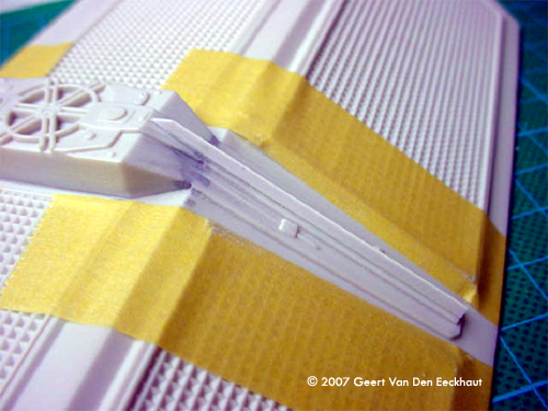
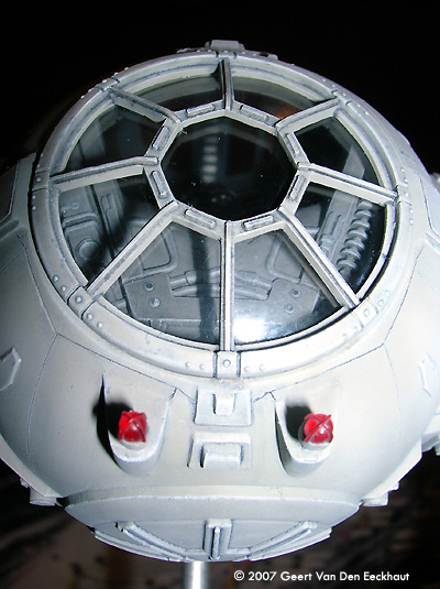
Step 7: Fuselage Upper Half. I dealt with all the boxes in step 4. I glued the hatch to the upper part of the fuselage half and started worrying for step 8.Step 8: Closing Up the Fuselage Well a new problem came in sight. The fuselage has two holes in the shape of a trapezium. Normally you should glue -before closing the two halves- four walls on the lower fuselage. These close the gap between lower and upper halves. I let the details on these parts inspire me to make my own. I first glued the halves together, then glued the walls in place. These were voluntarily made too large so that I could cut them to the appropriate size when installed. And then I got myself scratching the details so that these would become a point of interest for the viewer. The eyeball windshield- again I used the kit part as a mould to heat form a new one much thinner and much more transparent. You can glue this with Kristal Clear to its frame. Again I followed Ward's advice and rescribed all the panel lines, remember you have to create those on the eyeball itself, AMT forgot them. Use the drawings from the official Star Wars Fact File on the advanced Tie Fighter. The other parts left do not present a problem, just the back plate doesn't fit. I sanded this part down so that I rescued the details molded on this part which I glued to the new one made from plastic card. Step 9: Solar Panels Not much to be said. I sanded all the sides. They are too thick so I got them thinner, more to scale and replaced the small ribs on the outer side of the panels with new ones. Step 10: Blasters Once I bought a small set from Rocco with light bulbs in different colors: blue, red and orange. They were meant to dress up cars in HO scale. This set always came in handy. I cut off the plastic representation of the guns and put two new laser guns in place, made of transparent red plastic. Step 11 & 12 - In Flight Display Since I never meant to squeeze my Tie into a piece of Plexiglas, I skipped these steps. Done! And now the paint job. |
|
Painting I wanted to get my painting techniques(?) from under the dust. So I experimented a lot with different techniques like pre-shading, paint-chipping etc. This is what I did for the fuselage:
For the solar panels, I was looking for a kind of black that would give you the impression -depending on how the light shines- of seeing a bluish shine on it. At the same time it should reflect light without being too glossy.
|
Paints/Supplies:
|
|
Conclusion And done! I was satisfied. I hope that this article inspires you all to keep sci-fi modeling. It got me back on track. Enjoy modeling! |
![]()
This page copyright © 2007 Starship Modeler™. First posted on 26 April 2007.
![[Poor Darth needs more fiber in his diet]](gd_vader_frog_prince.jpg)
![[Please click to enlarge]](gd_vader_binnenkantgelakt.jpg)
![[Please click to enlarge]](gd_vader_front.jpg)
![[Please click to enlarge]](gd_vader_bovenvanachter.jpg)