
|
The projects in this section are presented as step-by-step journals. Our intent is to delve deeper into the nuts and bolts of constructing and finishing a particular project while giving a sense of how long it takes. The subjects will range from simple kits to complex dioramas and everything in between. Authors will range in skill level, and include hobbyists and professionals. If you have a project you would like to share here, please drop us a line to discuss it. |
|
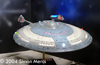
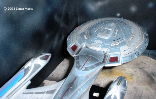
| Star Trek® USS Enterprise-E |
|
Project type: Kit with electronic components
by Simon Mercs - images & text © 2004 This project documents the construction of a standard kit with a lot of custom electronics added. The kit used was the standard AMT/ERTL USS Enterprise-E offering provided by the client. You can see more of Simon's work at his website: www.thekitfactory.com - Ed. |
|
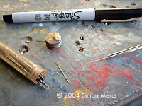
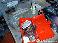
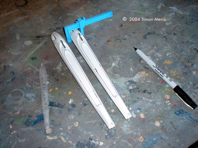
Image: Parts are freed from the sprues with specialized "sprue nippers". These have a flat side that enables you to cut right up next to the part. |
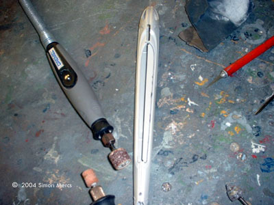
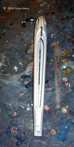
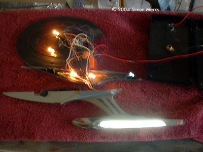
Day 1 The project begins like all good models: sanding of parts, clean removal of the parts from the sprues. Some old song by The Police, "Dancing on the Moon" is playing. The first real step is done to the Engine halves. This kit isn't a light up version, so they have to be altered. An exacto knife, Dremel Motor-Tool, and some very fine grit sandpaper helps accomplish the task. A template part is used to outline the location of the Lens that will be lit from underneath. I cut the plastic carefully, being careful not to cut or sand beyond the marked lines. Clamps are used during the tracing process to keep it accurate. The resulting cavity will allow 2 different LEDS and a CCFL (Cold Cathode Flourescent Light) or mini-fluorescent, to be installed and provide brilliant lighting. The system runs on AC/DC 120 Volt power supply, through several power inverters running the CCFLs. The rest of the LEDS and Diodes are on a 12 Volt circuit with their various resistors giving them proper voltage. Time spent today: 7 hours. |
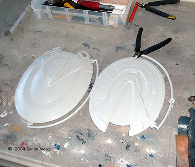
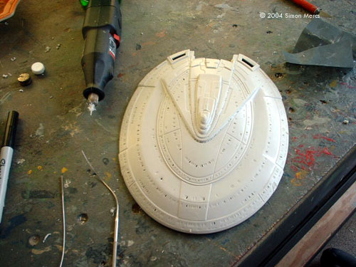
 ^ Very small drill bits Image: Starting in on the upper saucer Image: Lots of windows Image: Hacking and drilling complete Image: Light barrier applied |
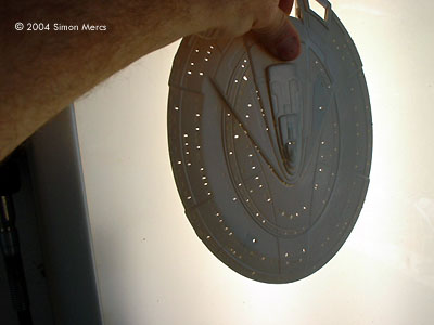
Day 2 Think Cheese on day 2: Lots of holes. Yes it's drill the tiny porthole day - much fun - using a drill bit just slightly thicker than a strand of hair. The trick is to drill on the top of the aperture, then the bottom. The 2 holes become a sort of "guide" With the bit in either hole, go up or down to the next. Letting the drill drift will cause a crooked slit. Keeping an even yet light pressure, gets you a very close-to-perfect window. This takes practice, and you will break these tiny drill bits until you get the hang of it. At $3.95 a bit, learn quickly! You can also use a "cauterizer", a small high-heated tip device used in emergency medical kits for a quick "suture". These are even more tricky and can seriously burn a hole out of proportion quickly. Not advisable for beginners. Once the holes are drilled and you have shaped whatever small imperfections remain with your trusty exacto knife, fine sand both sides of the Hull. Once the Hull sections with porthole/window lighting are done, you need to spray "lightblock" paint on all interior surfaces. Light shining through plastic ruins any illusion you are trying to achieve. 2-3 coats of flat black, sealed, are recommended. A good drying under heat lamps and a good seal will keep these from smudging later. It's tedious work that pays off big later. Time spent today: about 8 hours. |
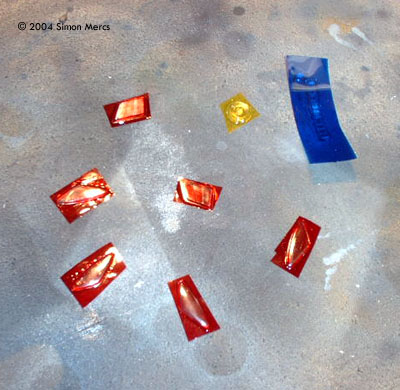
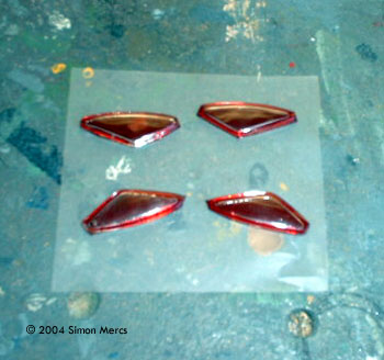
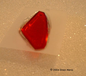
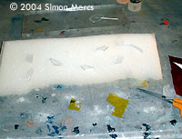 ^ Getting started Image: The colored gel is cut roughly to size Image: Colored pieces covered Image: Excess trimmed back, it's time to apply the other side Image: Closer look Image: Put in place Image: How it looks from the outside |
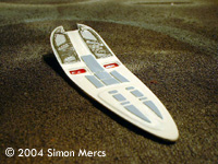
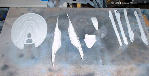
Day 3 Today I concentrated on "gelling" the parts that need coloring: the clear parts that require lighting in a special shade. I use Theatrical Gel material that we used in stage shows. This is heat resistant Mylar-like material that can be used to filter light in a multitude of ways. When using very bright lighting it enhances and gives rich, even colors. I use it in many of my props and kits. Using 2 stage epoxy I bonded the gel to the inside of each clear piece. Once dry, another gel filter of a "hazy" white effect was added to the colored gel, to make the effect more like the studio version. The hard part is not getting any bubbles in the resin mix by pressing with enough pressure not to push all the resin out, and get an even look. Once dry, all these are flat coated to get rid of any "plastic" sheen. Light will shine through with a rich energetic color but not allow viewers to see into the "works". These were then all installed in the hull sections where they belong. Once I begin to paint external details, they will be masked with lo-tac Frisket. Time spent today: 7 hours. |
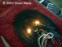
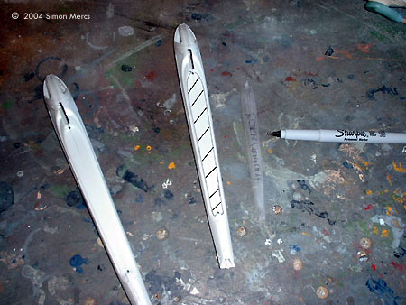
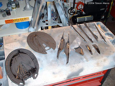
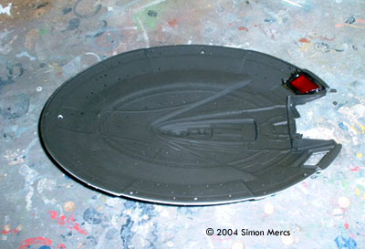
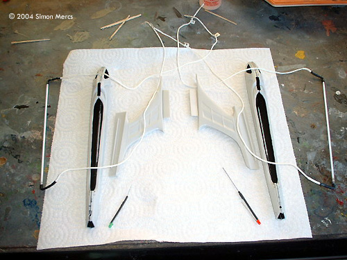
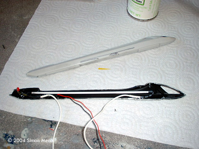
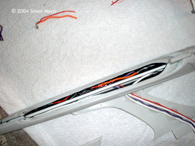
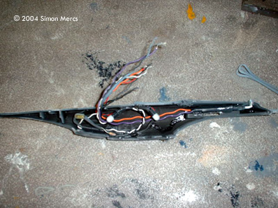
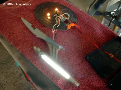
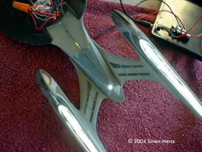
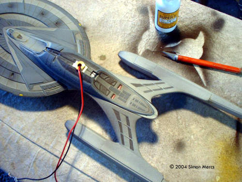
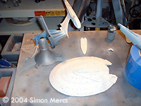 ^ Painting the base coat Image: First, I need to plan where the warp engine CCFLs and wiring will go Image: I mark on the inside of the pylon the route for the wires Image: Flourescent and red LED in place Image: Red bussard collectors are affixed ... Image: ... as are the impulse engines Image: Stern nav beacon |
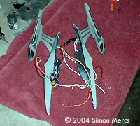
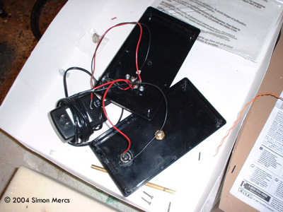
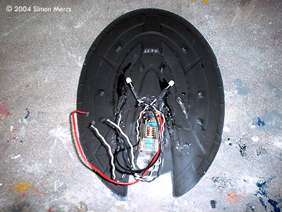
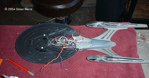
Day 4 Today I continued with Primary color application on the outer hull sections. I also began to install electronics that will light up this prop. Without getting into major details, this involves a lot of "tests" to ensure the lighting is effective at adding to the realism of the prop. I continually adjust the placement, pitch and angle of the lights now and finalize where all the wires will run. This is a long process and all builders have their own methods to check these things. I do as many as 100 light tests during the assembly of any starship model because once you have it all together, there's no going back. Time spent today: about 12 hours. A long day. Image: Wiring is epoxied to the inside of the pylonImage: Warp nacelle with lights and wires Image: Power supply is wired up Image: Special lighting and the circuit board that controlls the blinking lights is affixed to the lower saucer half Image: Nav lights affixed to the upper saucer half Image: Secondary hull lighting |
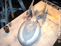
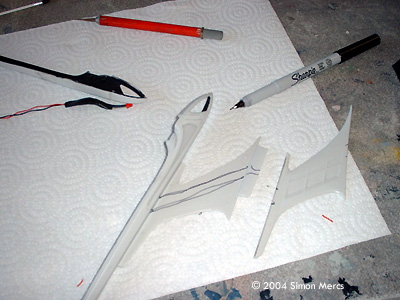
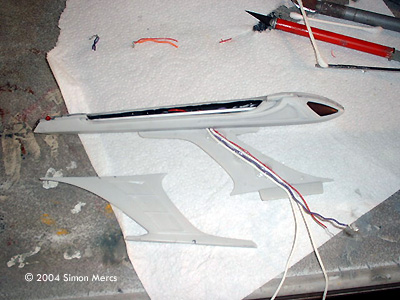
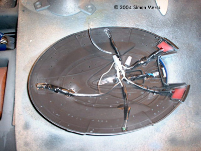
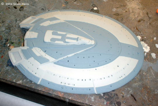
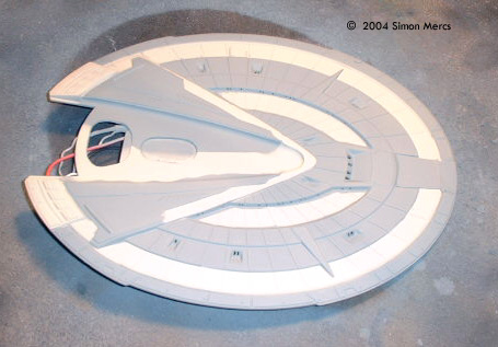
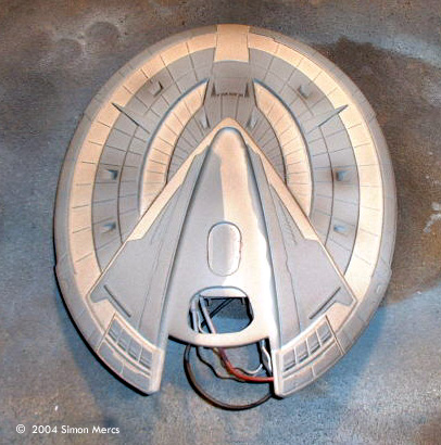
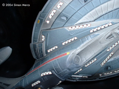
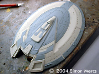 ^ Upper saucer after first round of masking Image: Closer look Image: Secondary hull Image: Warp engine gets a base coat Image: Underneath the saucer Image: A little bit of weathering goes a long way (note: picture has been "enhanced" to bring out the shading). |
Day 5 Day 5 consists of some old "Alice Cooper" on the blaster and a lot of work. This is the external paint application section of the build. It's very time consuming as it requires you to cut "Lo-Tac" frisket to airbrush all details on the outer hull, per file photographs of the studio model. The correct colors are chosen and many X-acto blades are expended in this process. I swear a lot during this process. Good masking skills take many years to perfect (all builders out there can sympathize with that statement). The more you do, the better you get. Also notice the many steps to get the Engines done correctly. It requires patience and dedication to the craft to do the best you can. Some "weathering" enhancement unifies all the colors and adds a touch or "real space" look at the end. Time spent today: 10 hours. |
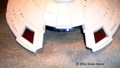
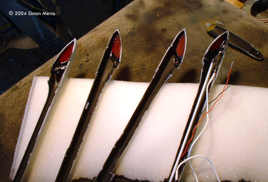
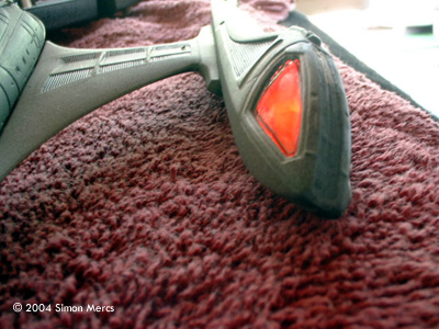
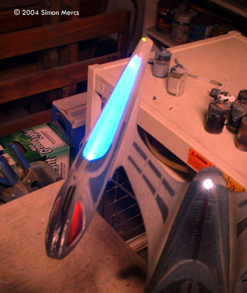
 ^ THe devil, as they say, is in the details .... Image: Finished pieces ... and a broken one Image: Here's the one I didn't break affixed to the secondary hull Image: CCFL works Image: Bussard collector is looking good |
Day 6 Going by file photographs of the studio miniature, I continue to paint the fine external detail by hand. I don't airbrush everything as many people assume. Seventy-five percent of the paintwork is hand applied. I use airbrushes to do priming, weathering, and sealing, and some base coats. The parts begin to get fewer and fewer, as the light tests start again. This project requires diligence on the builder's part, as wires are easily bent or broken during assembly. Notice one of the engines is not built yet. Why? Because I broke the 6 inch CCFL bulb during assembly, a very fragile component I tried to move too roughly. Live and learn. Time spent today: 9 hours. |
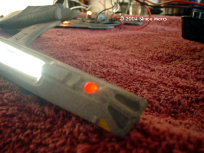
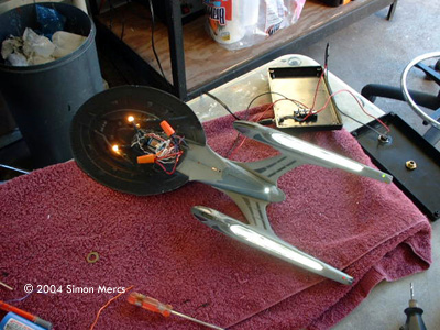
 ^ Upper saucer LEDs work .... check. Image: Position marker light works .... check. Image: Nothing starts smoking when power applied ..... check. Image: Impulse engines light .... check. |
Day 7 Today Duran Duran is wailing on the blaster; gotta love that 80's sound out. I continue with the last of external detailing and the many tests on my electronics required at this point. I make every model differently: this one has a very detailed shuttlebay area. The last had a lit photon array. I want each client to have a very unique piece so I do various different things to each kit so that no two are the same. This makes each piece special and collectible. Time spent today: 7 hours. |
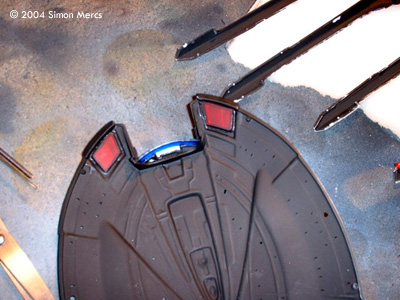
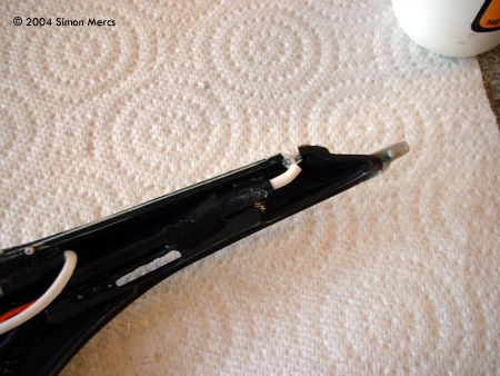
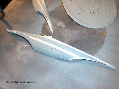
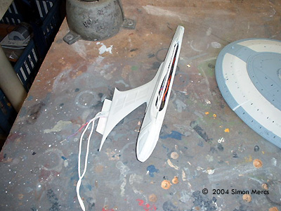
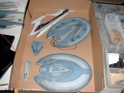
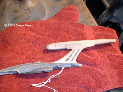
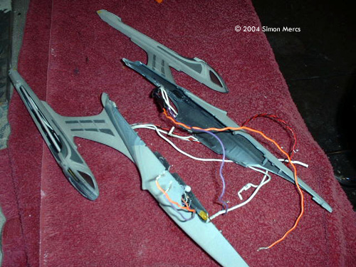
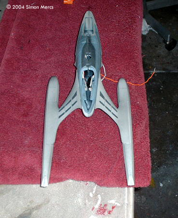
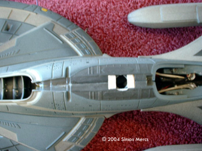
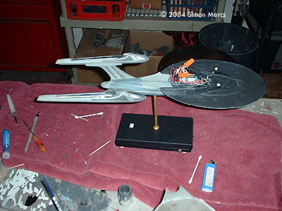
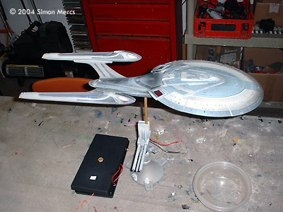
 ^ Other warp nacelle fixed and attached to it's hull half. Image: Closer look at the above Image: Engineering hull halves glued together Image: Seam reinforced with epoxy, and lower saucer half attached Image: Building a support for the tube that will connect the model to the stand Image: Optimizing wire lengths |
Day 8 Today I finished the second warp engine and matched it to the first one. Then the engineering hull was assembled, with the warp engines already installed. The lower saucer section was glued onto the engineering section, followed by a few light tests. The stand/rod assembly was created and epoxy applied to the seam to strengthen the prop. The wires are shortened and optimized for placement in the saucer section. Light leaks were fixed as the assembly proceeded.The last few parts that seal the engineering section were affixed and light blocked. The brass female coupler was then installed in the base of the engineering section and the main power lines strung through it. The light tests continued throughout to make sure all systems are functional. Time spent today: 7 hours. Image: Everything still worksImage: Gonna have to fix this leak .... Image: Brass couple in place and wires run out Image: On the stand |
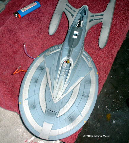
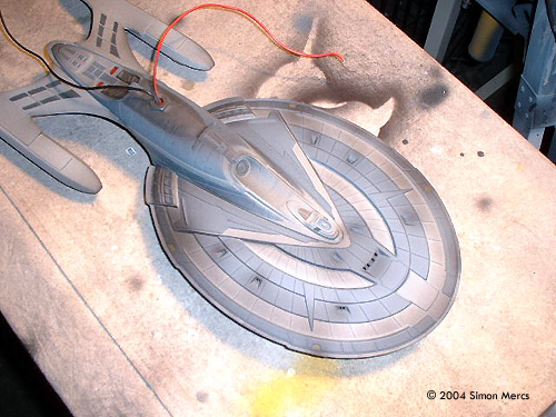
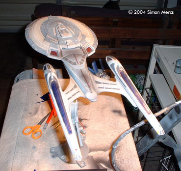
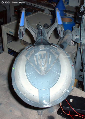
 ^ All she needs are finishing touches Image: Larger view, similar to above Image: Underneath Image: Tinted blue plastic inserts cover the CCFLs and finish the warp engines Image: A clear gloss coat readies the hull for decals Image: Lights work |
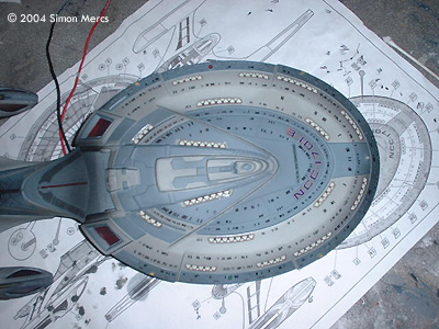
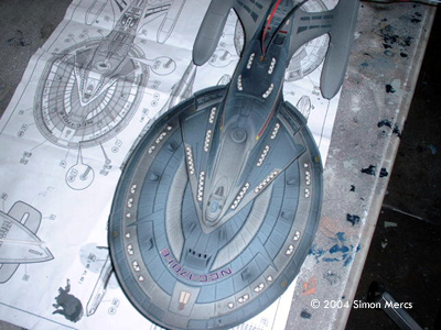
Day 9 Almost done! Today I glued the top saucer section on and connected the last of the power leads to the few remaining lights. The seal is tight and strong. A few more light tests confirmed the assembly is successful and all systems are go! Next I proceeded to darken the saucer and hull windows, and the last but not least, decals! There are a lot of decals on this kit and slow, careful application is required. I use tweezers, cotton swabs, and patience when applying decals. I use only as many as needed to add the extra details required to finish the piece. Time spent today: 8 hours. Image: Close up of the starboard warp nacelleImage: On the stand Image: Decals, topside Image: Decals, underneath |
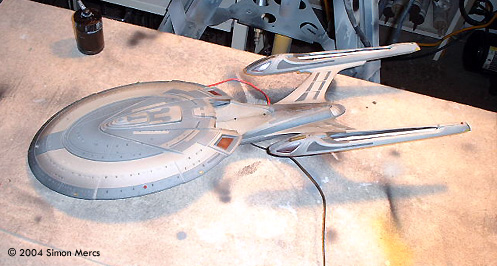
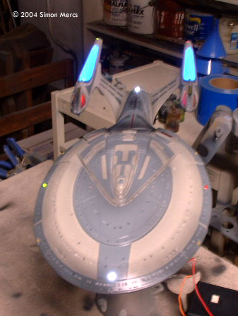
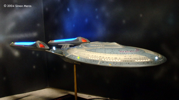
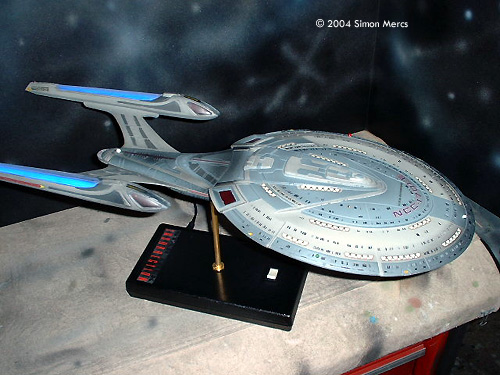
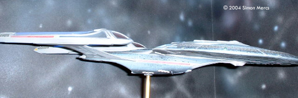
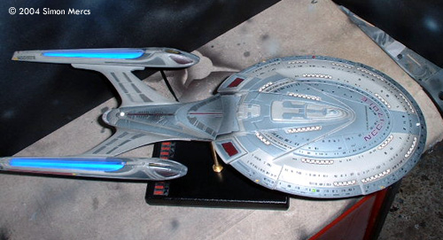
 ^ All done! Image: Right/front view (lighted) Image: Looking down Image: Starboard side |
Day 10 Day 10 finishes the model up! It used to take me 12-15 days to do one of these, but as the orders keep coming I get faster. I can see getting to the point where it takes me 7-9 days to finish one in the near future. But speed isn't the issue, good results are. Here's a few parting shots of this very cool model. Thanks for joining me on another modeling exercise. Photo shoot time spent today: 3 hours. Image: Underneath, closeupImage: Another top view Image: Shuttle's eye view |
![[The universe is a big place - and so is this site. Here's a map]](http://www.starshipmodeler.com/resource/sm_sitemap.GIF) |
| Visit our sponsors! | Advertise with us |
![]()
This page copyright © 2004 Starship Modeler™. Last updated on 8 November 2004.