
|
The projects in this section are presented as step-by-step journals. Our intent is to delve deeper into the nuts and bolts of constructing and finishing a particular project while giving a sense of how long it takes. The subjects will range from simple kits to complex dioramas and everything in between. Authors will range in skill level, and include hobbyists and professionals. If you have a project you would like to share here, please drop us a line to discuss it. |
|
| Flying Sub |
|
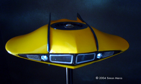
![[All done]](sm_sub/09_200.jpg) |
Project type: Kit with Lighting/Electronics
by Simon Mercs - images & text © 2004 This project will start with a Monogram "Flying Sub" model and add a blinking instrument panel, plus lighted berth, cabin area, engines and forward searchlights. It will also include a fully detailed interior and pilots, and rest on a power base. |
|
|
|
|
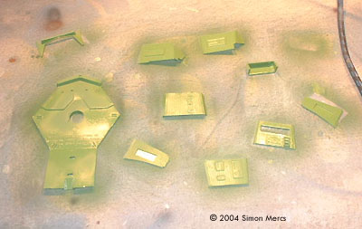
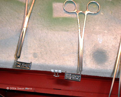
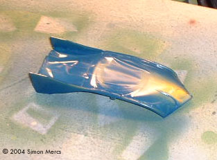
Image: Interior bits, ready for paint .... Image: ... and painted. Image: Hemostats make good holders for small parts - you can paint them without having to actuallt handle the part. Image: Frisket (a clear, low tack, adhesive-backed material found in art supply stores) makes an excellent masking medium. |
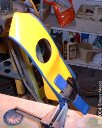
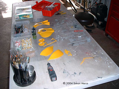
Day 1 A journey of a thousand miles ... begins with the same steps: Cut away parts to be pre-painted. Sand and cut away flash and all that gook. Clean and check all parts. Check electronics supplies so you have enough, then set aside for now. Once this was done, I began painting the interior/cabin panels and the exterior striping details. When airbrushing details, I use a good quality frisket masking material to protect areas not meant to be painted. This process is crucial to get right, or paint will seep under the mask and ruin the finish. It's a good idea to press the frisket flat as possible with a blunt wooden tool, to get creases and bubbles out. A toothpick run in the corners will help stick those edges down better. Spray your paint lightly, as thick coats run and blob. It's much better to do many light coats than one thick one. Time spent today, about 8 hours. |
|
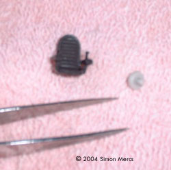
Image: Two pieces must be drilled out Image: Preparing the engine parts Image: LEDs installed in the engines Image: What the viewer will see |
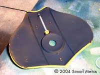
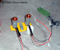
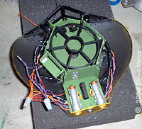
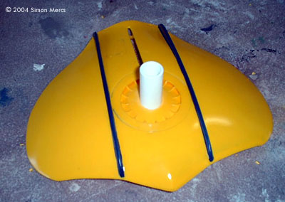
Day 2 I started today by removing the frisket masks from the top and bottom Hull pieces. The results of yesterday's work: not bad. A smear here and there, but easily cleaned. Before I can start to build the interior, I have to get the location of the stand "stem" figured out. Since the interior sprawls all over the cabin, you have do it at this stage. It's a bit like Chess, you have to think many moves ahead. The female part of the coupler was cut down and pre-drilled to allow the wires running from the power base to go throughout the model. The cabin floor "diver's hatch" was altered to allow those same wires to pass through under the floor. The top of the coupler must be flush with the floor to allow a detail "hatch" to cover the connection/stand point. This will be apparent later on. The engines, which light up in the rear of the sub, were prepped to test fit the LED Diode that will be installed there. The engine parts are very small, less than 2 inches (50mm) long when assembled. The drilling must be accurate - an off-center hole will ruin the effect. The leads will go into the floor, through pre-drilled holes in the engine bottom sections, and will hopefully be almost invisible. Time spent today: 9 hours. |
|
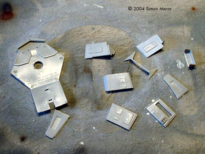
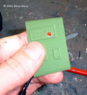
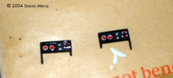
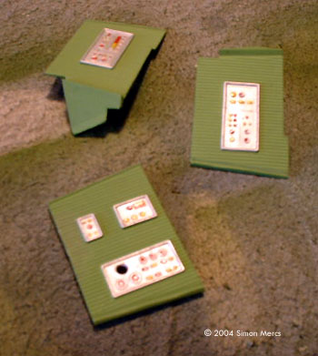
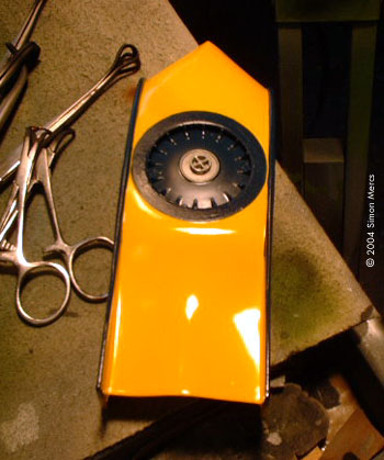
Image: Fitting LEDs to a control panel Image: Small painted panels Image: More control panels Image: Working on the little man |
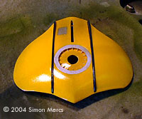
Day 3 Today, I have finished with the detail and pinstripe paintwork on the upper and lower Hull sections. I have done some weathering effects to the bottom hull. Later this will be refined and a "barnacle" damage effect will also be added. Next, I started work on the control panel that gets the sequenced (on/off) red LED. Pre-drilling and test fitting helps in the assembly process down the line. Also at this time, the control panel in the engine room was detailed. This measures less than an inch long and requires a lot of patience to get right. After that, I did more pre-painting of the remaining parts, and the figures of the pilot and co-pilot. The green color is"green zinc chromate"; the blue is "sea blue". The control panels in the cabin area were detailed with various colors to enhance the "winky blinky" effect. Metal parts were painted in"steel" and all exterior parts were sealed in gloss (the interior was sealed with a clear flat). Total time spent today: about 10 hours. |
|
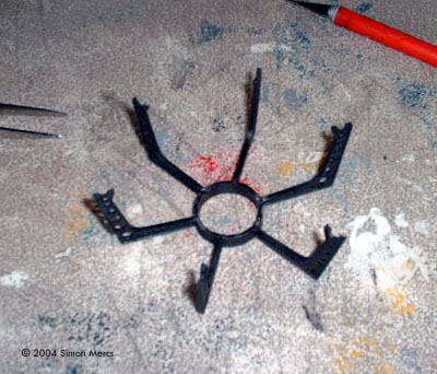
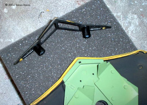
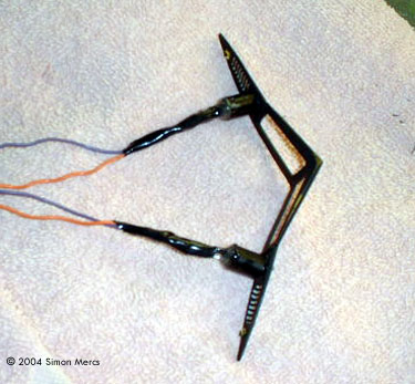
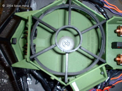
Image: Itty-bitty chairs Image: "Roll cage" assembly Image: Headlight "conduits" added Image: There's a distinct copper color on the engine details |
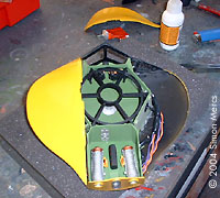
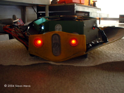
Day 4 Today I continued with work on the internal panels and details. The tiny command chairs the pilots sit in were assembled and painted. The "roll cage" was pre-assembled for fitting later. This is a tough assembly unless you build it first and then place on the floor section. Do it the other way and you'll see why. Very often you run into the problem of the top of these structural "rollbars" being too high and preventing a good top section fit. This is not a great kit, and it never had a good-fitting top section. I have made several with a limited forward interior, with the top glued on and closed up. That's the only way you get a perfect fit out of this kit. The forward "visor" section was fitted with small tubes to prevent light leaks from the forward headlamps. They also help in the assembly and centering of this nifty detail lighting. A lot of parts have been pre-painted at this point. It was a shorter day today; lots of running around to do, getting aints and other supplies to keep the Kit Factory going. Time spent building: about 6 hours. |
|
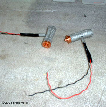
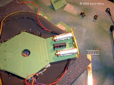
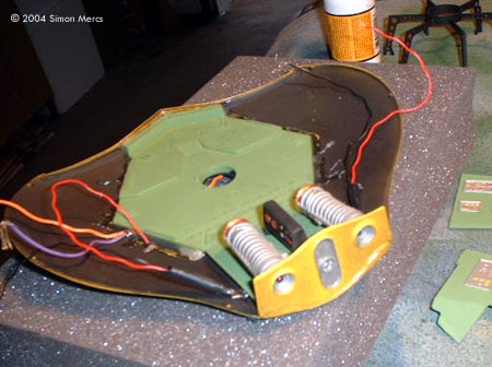
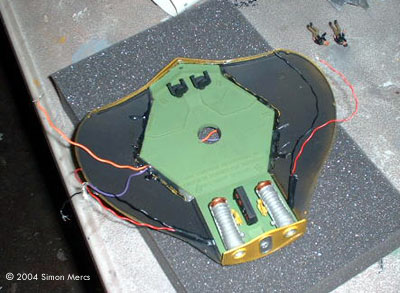
Image: The headlights, installed Image: Bottom of the hull Image: Engines, installed Image: Another view |
Day 5 Moving on, I started to work on assembling the rear engine area. This is needed to find a hiding spot for the wires in the floor. Assembly instructions don't apply to a conversion like this. All electrical fittings have to be pre-determined to make sure all will work later. As I did yesterday, blacking out the interior cavity will prevent light leaks from numerous LEDS going into this model. The forward searchlights were pre-glued in their chambers. Great for blocking leaks and positioning the LED in the very center of the headlamp frame, re-enforcing the illusion. Each LED must have its negative and positive leads soldered securely. Loose connections are no fun later when you can't get back to them. Today you can see how all the pre-painted and illuminated parts are starting to come together in that Engine section. Time spent today: 8 hours. |
|
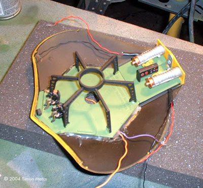
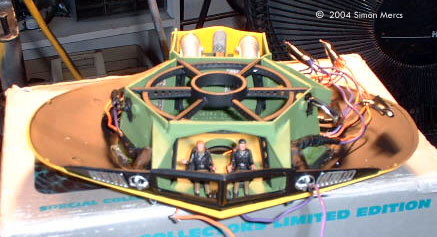
Image: Starting point Image: Major sub-assemblies installed Image: Lights work |
Day 6 Today I concentrated on getting the basic internals installed. This includes the "roll cage", the pilot's chairs, and the pilot figures. I've built this kit several times over the years, and learned the hard way the fit is problematic. When building the interior, make sure the floor is well pressed down to the bottom hull section. I usually bend the engine section up a bit to make sure the fit is tight. Or you run into the problem of the top of the structural inner "rollbars" being too high and preventing a good top section fit. I also spent time working on the electrical system and doing some light tests to check all connections after gluing and soldering. LEDs were glued into place and then the area around the join was painted flat black to prevent light leaks, a major preoccupation with any illuminated prop. The Red LED in the control panel is a sequenced one, or a "blinky" as I like to call them. The others are white illumination LEDs and some amber/red ones in the engines. Notice the wires are strung under the small gaps under the rear section of the floor. Time spent today: 7 hours. |
|
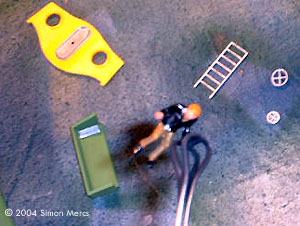
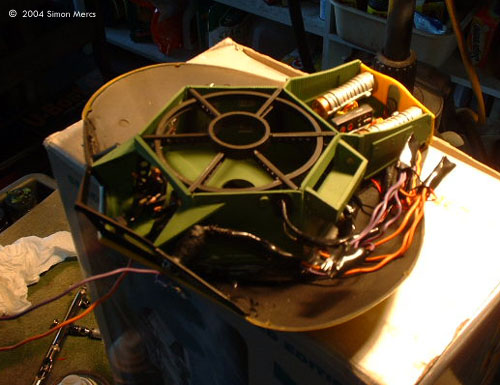
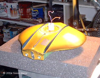
Image: Lights are still working Image: Front view Image: Only two wires will exit the model Image: My custom hatch Image: In place |
Day 7 On this, Day 7 of the project, I worked on the wire harnesses and securing all the electrics for enclosure. The little hatch part that I must use to cover the post entry on the bottom of the floor was then created. Using an extra part off the Polar Lights Enterprise (deflector dish) turned upside down, with an extra round handle from another Flying Sub kit, I made a very decent part. This will fit neatly over the aperture and add a little detail that is not included in the kit. The ladder, however, was nixed as it will not work in this setup. Then I preparred and test fit the top side sections of the outer hull prior to attaching. Lights were tested often during the procedure to make sure no problems arise after assembly of the outer shell is completed. Time spent today: about 5 hours. |
|
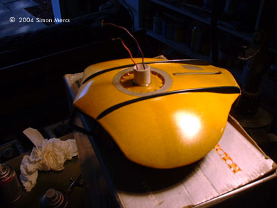
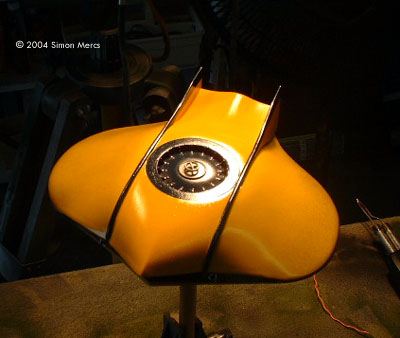
Image: Underneath Image: Bow Image: Top view, all buttoned up |
Day 8 Getting close to completion now. Today I concentrated on finishing up the hull and getting it "together". The two upper side hull sections were attached and the edges are sanded down to get a nice clean "fin" edge. The entire hull received repeated thin coats of clear gloss to protect the piece and enhance its eye appeal. It was mounted on a "Panavise" which is a wonderful modeling tool. This allows stable handling while the base is prepared. Light airbrushing of a dark "exhaust" colors were added to the bottom edge center, and below the rear engines. This bit of weathering effect looks like the bottom of a real seafaring vessel. I also lightly brushed on a bit of epoxy compound on the bottom near the center lines to get a "water/barnacle" effect like I have seen on countless real ships and submarines. Not to much on top, but a real nice touch on the hull below the "waterline". It's many little things that really make the prop interesting. The windshield was also attached with a special glue that dries clear. No smudges pleeeeeze! Time spent today: 7 hours. |
|
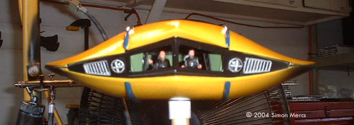
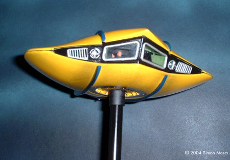
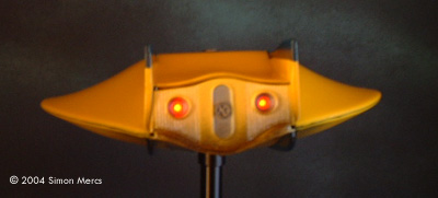
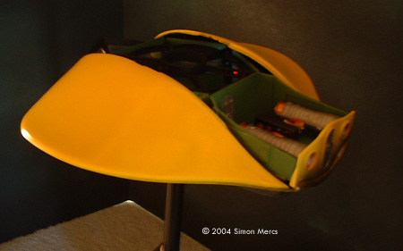
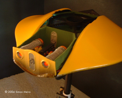
Image: Front view Image: Lights on Image: Stern view Image: Left/rear view, with the top off Image: Right/rear |
Day 9 Well that is it! I am finishing up here today! The stand assembly was completed ahead of time and the last details are set right - a little touch up here and there. The stand's post was painted in a flat black enamel. The lights were tested once more and a small set is put up to take a few shots of this sweet model "in action". This most enjoyable session lasted 5 hours. I hope you enjoyed this project. It has been delivered to the client and he is extremely pleased at the results. Thanks for your continued interest. -- Simon Mercs |
|
|
|
![[The universe is a big place - and so is this site. Here's a map]](http://www.starshipmodeler.com/resource/sm_sitemap.GIF) |
| Visit our sponsors! | Advertise with us |
![]()
This page copyright © 2004 Starship Modeler™. Last updated on 21 June 2004.
![[Box]](sm_sub/01_03.JPG)
![[Click to enlarge]](sm_sub/06_104.JPG)