
|
The projects in this section are presented as step-by-step journals. Our intent is to delve deeper into the nuts and bolts of constructing and finishing a particular project while giving a sense of how long it takes. The subjects will range from simple kits to complex dioramas and everything in between. Authors will range in skill level, and include hobbyists and professionals. If you have a project you would like to share here, please drop us a line to discuss it. |
|
| Star Wars® Millenium Falcon |
|
![[Box]](sm_mf/mf1.JPG) |
Project type: Kit with electronic components
by Simon Mercs - images & text © 2005 This will be a longer build than usual for me. I will accurize the basic (and old) MPC/ERTL kit using a lot of aftermarket parts, plus add full lighting. |
|
Day 13 | Day 14 | Day 15 | Day 16 | Day 17 | Day 18 | Day 19 | Day 20 | Day 21 |
|
|
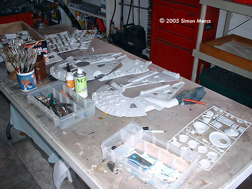
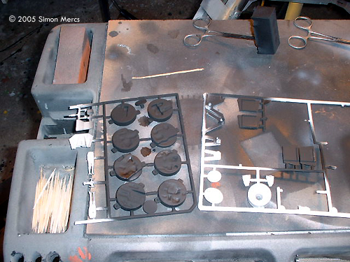
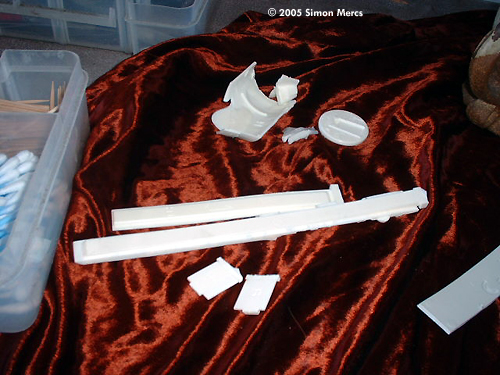
Image: The first step is to invntory everything in the box and familiarize yourself with the instructions |
Day 1 Basics are fundamental and the cleaning and sanding of parts is the first order of the day. Nothing exciting yet, but you have to do this dull stuff before you get to the good stuff. This process applies to all the parts. Also a good time to make sure all parts are accounted for. Try playing some "Enigma" in the background, it helped me a lot. Time spent today, about 6 hours. |
|
|
|
|
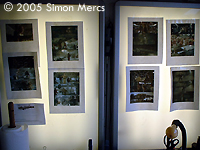
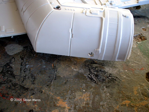
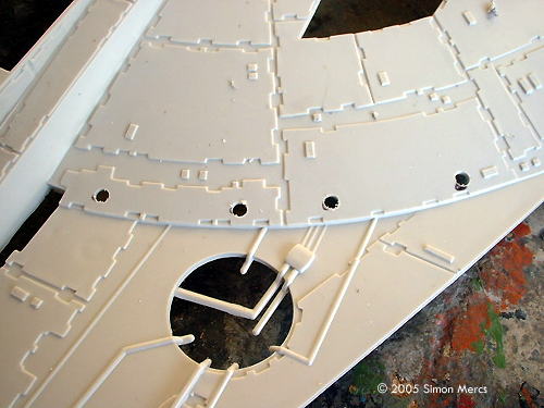
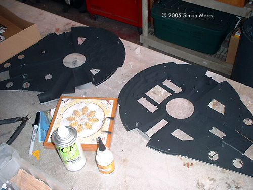
Image: Closer look |
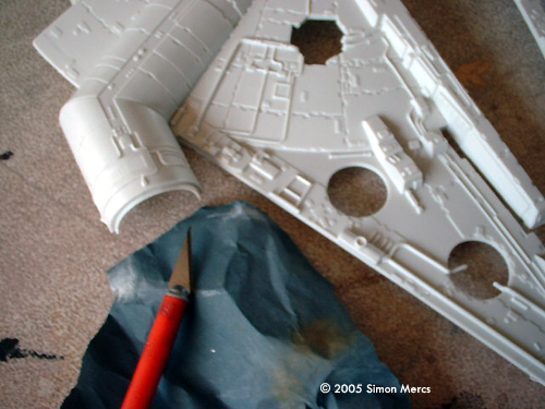
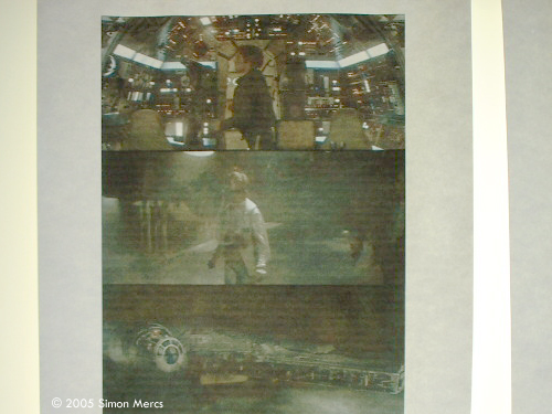
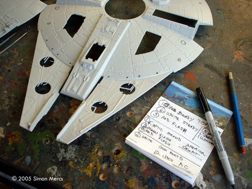
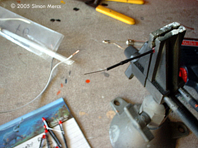
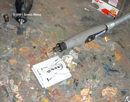
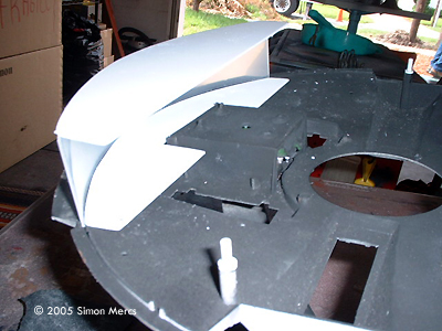
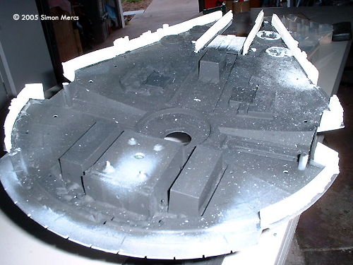
Day 2 Today we start to use the reference material I have and some sent in by the client. A lot of good shots are put on the backlit display so I can plot drilling for the eventual lighting. Careful measurements and a good eye are invaluable at this stage. This is ordered to be a "Prop" quality version of the Millennium Falcon, full lighting and a special "Weathering" package. A lot of homework to do on this model. The paint stage requires a lot of other reference material of close-ups of the actual prop. But one step at a time. With the light plot all figured out, I begin to drill out the holes (3mm) to allow the later placement of the lighting system. This model will have several different systems and different bulb sizes in the exterior Navigation/Landing lights array. A thick layer of black "blackout" paint goes on all the hull parts that will have lighting within them. This is a mix of my own invention and uses some powdered rubber compound to really block out any potential light leaks that ruin the illusion. The cockpit canopy requires 4 additional struts to be accurate, as the MPC kit does not make this correctly. Four tiny styrene struts are carefully cut and glued within the existing part to make it accurate. Time spent today, about 9 hours. |
|
|
|
|
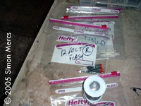
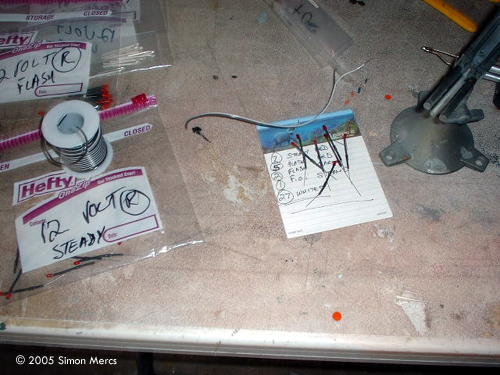
Image: Many LEDs in many sizes Image: Preparing the wires |
Day 3 Today I am soldering the many LEDs and their respective resistors to have them ready for assembly. The client has ordered many after-market parts for this project, so I must build in segments that can be dealt with in the meantime. This model has a lot of electronic "goodies", so this stage can take several days. The rear cockpit wall will be highly detailed with many strands of fiber optics to really give the viewer a "feel" of looking into a real functioning control room. Once the after-market parts arrive, we will be switching into high-gear and begin assembly. This will be followed by paint and detailing. Time spent today, 10 hours. |
|
|
|
|
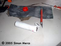
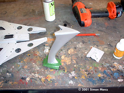
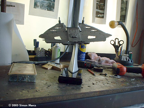
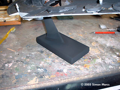
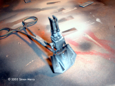
Image: The stand, roughed into shape |
Day 4 More electronic soldering today. Then, on to the Stand/Base unit. The weight of the model and the client's requirement that it be "coming in for a landing, landing gear deployed" requires me to do some sculpting and a little engineering. Finding the point of balance requires some time, then figuring out an assembly that will be very strong, yet flexible and visually pleasing is a challenge. I went through several tests until I found the perfect system. Using an old Playmates stand, and hiding the coupler in the battery compartment this kit used to have in its first release, I rigged a strong, epoxied and bolted assembly that will do all the client has requested. The shape of the arm was altered using super-strong epoxies that allowed me to shape and sand the stand into a very cool shape to add to the overall presentation of this piece. This took quite some time as it is a "scratchbuilt" concept. The stand is not removable as this is meant to be a showpiece, not a toy. Hopefully the client will put in a presentation case as it is designed for this. Time spent today, 11 hours. |
|
|
|
|
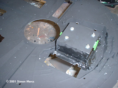
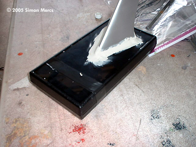
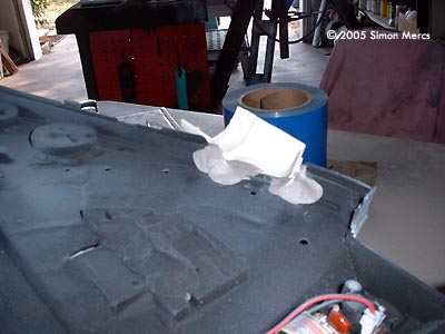
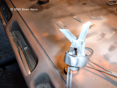
Image: Basic stand is complete |
Day 5 More work on the Stand/Base unit today. Sanding and sweating is the operative work of the day, as it is in the 90's in Florida at this time. The epoxy work continues and the stand is "merged in" with the model. I want this to be as discrete a connection as possible. All the bolts and such are internal not to ruin the illusion I am trying to create. After 2 days I believe I have the look I was shooting for. Time spent today: 6 hours. Image: Battery box gets light-blocking paint as well |
|
|
|
|
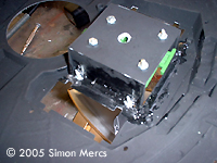
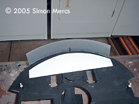
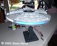
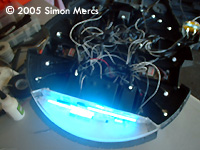
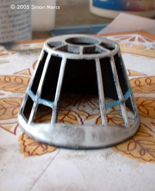
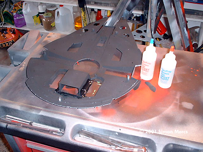
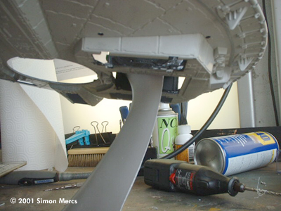
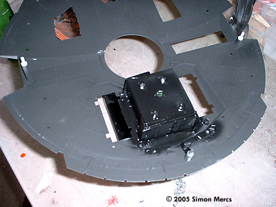
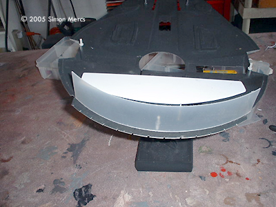
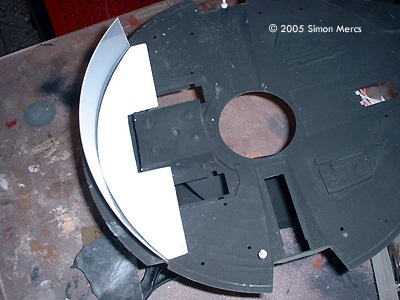
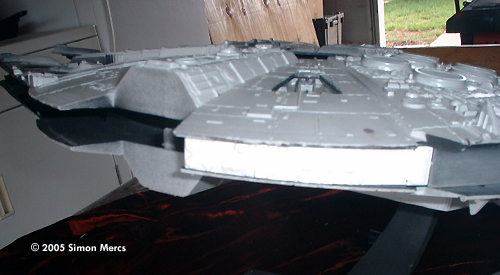
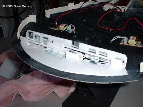
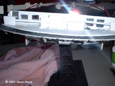
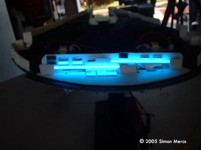
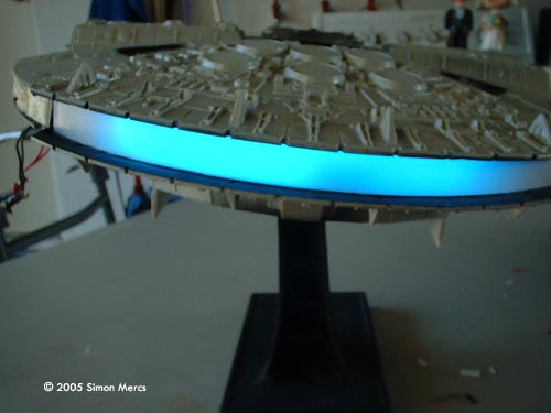
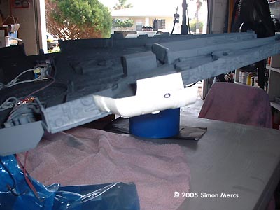
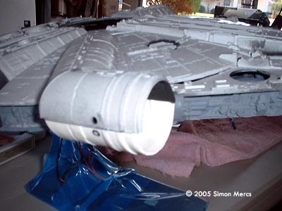
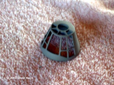
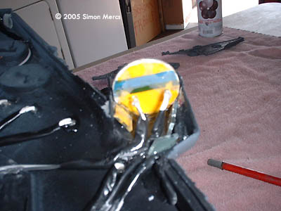
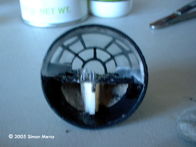
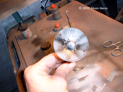
Image: The white styrene pieces reflect light through the translucent diffuser |
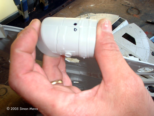
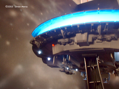
Day 6 Editor's Note: Some time elapsed between the last update and this, while Simon was waiting for parts to come in. Aftermarket accurizing parts are coming in next week, so I'm now resuming the build. The "lightbox" that holds the CCFL bulb is provided by VoodoFx.com. The bulb was upgraded from a 350mA to a 1250mA, as the kit provided bulb was not bright enough. Some modifications to the lightbox were needed as my stand assembly uses a "shock absorber" housing in the same section. The blue glow is quite even in the light tests -- unfortunately, digital photographs don't look exactly the same as in person. Some dark room shots give you a better feel of the look of this feature. Test fits indicate the box fits correctly in the model and should look seamless after construction. Time spent today: about 8 hours. |
|
|
|
|
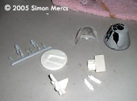
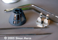
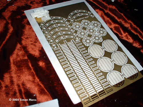
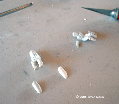
Image: Etched details |
Day 7 Today I am working on the aftermarket parts. These are made of resin, metal tubing, and laser etched brass. All resin parts must be cleaned so the casting residue doesn't prevent good paint application. Their defects and flash must be sanded and filled. Some test-fittings show the height of these alternate side panels reduce the height of the model, and alter the entire hull structurals. In essence, the entire kit is "cut down" in height to be closer to the original ILM prop. Time spent today: 8 hours. |
|
|
|
|
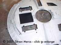
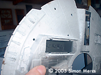
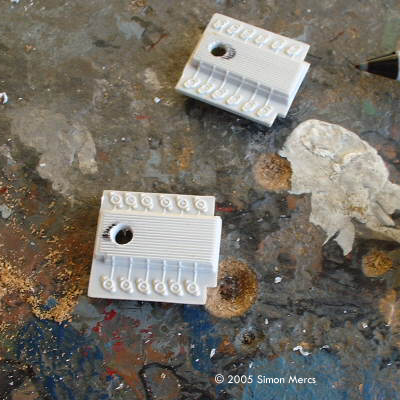
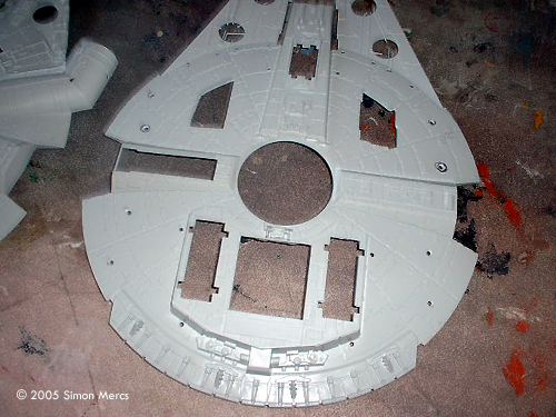
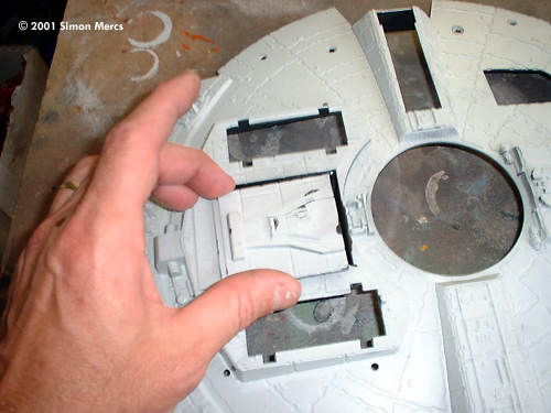
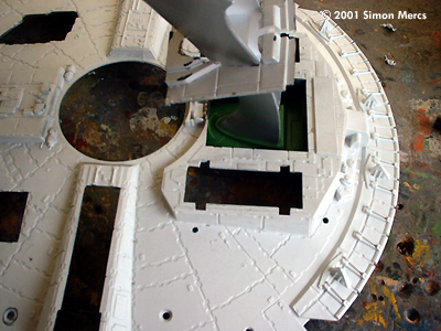
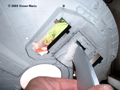
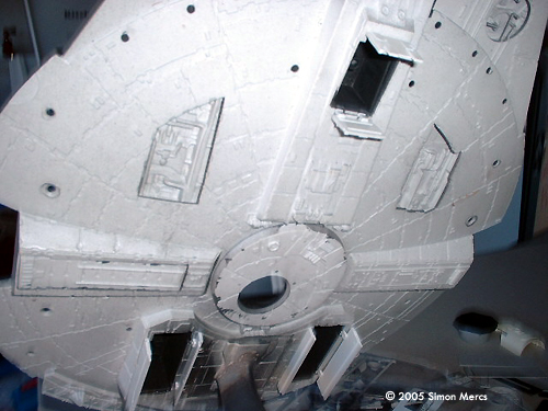
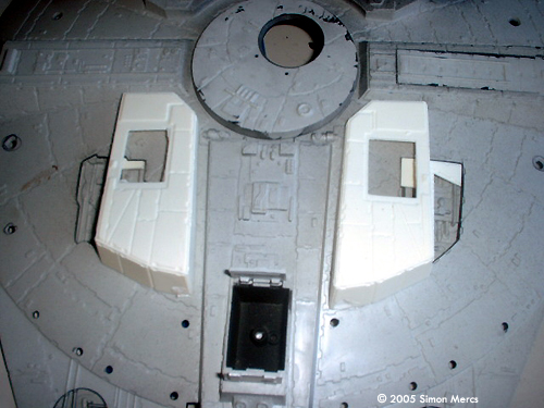
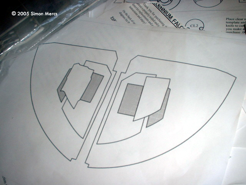
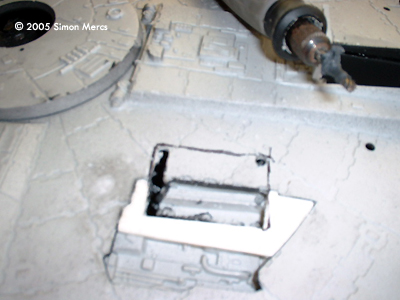
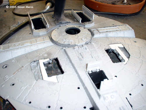
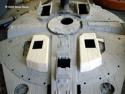
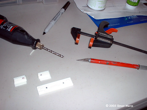
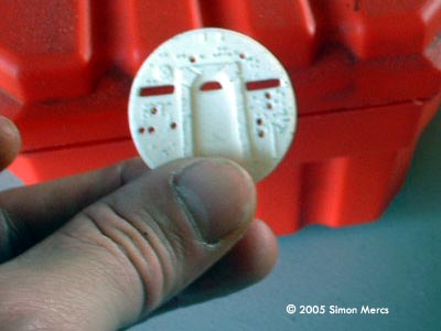
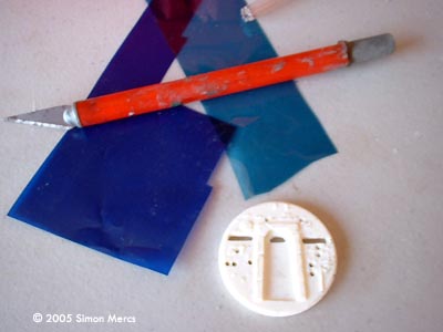
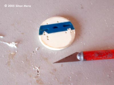
Image: Gear bays are secured with epoxy |
Day 8 The landing gear bays must now be placed and attached on the bottom hull section. This will enable me to place the lighting inside the perimeter of the work in progress. There's a problem, though: the ERTL kit only comes with 3 landing gear bays. The original prop/studio version has five. The after-market kit supplied by Falcon.com resolves this issue with excellent parts that blend in with the kit and make it accurate. As you can see in the photographs, the need to remove sections to allow the Bays to seat correctly. The "filler" sections that go into the hull recesses have an alignment slot that helps correctly place the bays. Once enough of the hull bottom is complete, we can move on to the side sections. I have left the landing legs off for now. This will make it easier to have a nice finish on the primer and primary color applications later on. Time spent today, 6 hours. Image: The detailing flawlessly mimics the rest of the kit's |
|
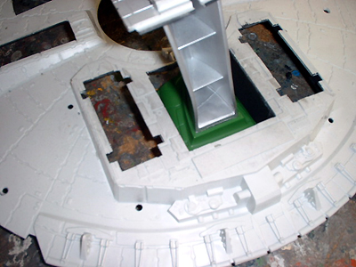
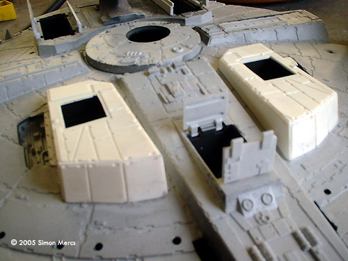
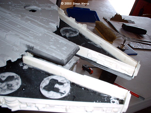
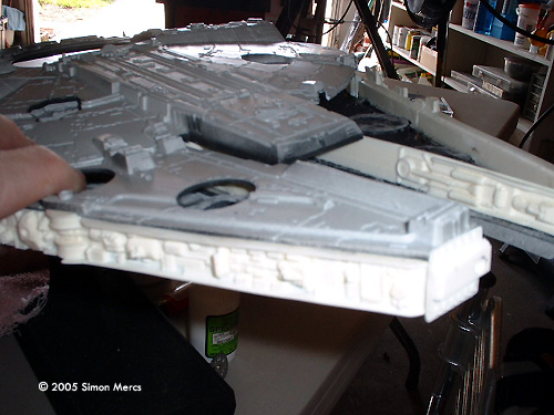
Image: Piece by carefully-test-fit piece, the side walls take shape |
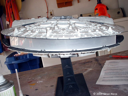
Day 9 Side sections are now placed according to instructions supplied by Falcon. This is a tricky process as you have to place the top hull section each time to get a good average center location for later assembly. You sort of have to think a step or two ahead as you do this to make sure all will fit later. Gaps and seams will have to be filled to prevent light leaks.The "airlock" sections will have to be trimmed down eventually, as the height of the prop has now been reduced by just under 1/2 an inch (13mm). As I go through this process I start to see that the sleeker Falcon being produced will be a lot more accurate in contour and overall look. I cannot stress enough the value of a lot of test fits as you go piece by piece. Taking the time will pay off big later. Time spent today: 7 hours. |
|
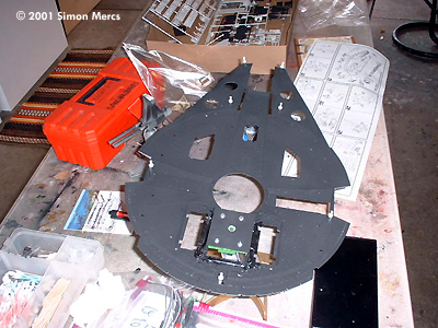
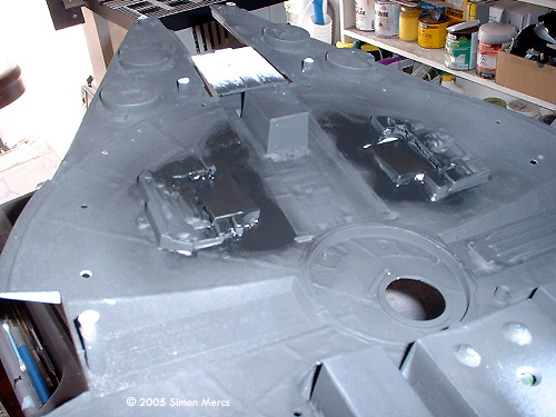
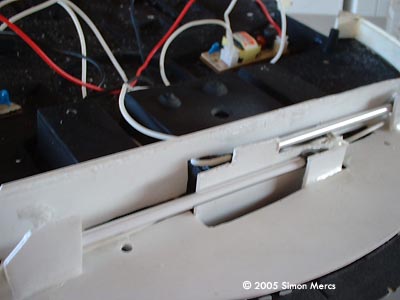
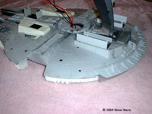
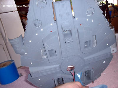
Image: Several parts have to be drilled for lighting |
Day 10 The side section assembly continues. As most of these are in place, I now must consider the top hull section. The alignment of the top and bottom pieces are so-so. With all the modifications, the mandibles are not quite lined up correctly. This is solved by making these an independent section. This accomplished, we have a lot more control on fit. The round recessed sections that detail the top and bottom mandibles must be trimmed down as well. These are too thick for the lowered side sections and prevent a good fit. Some fine sanding and trimming get the mandibles straight and level on each side. These sections will be blended back to the round Hull section when we seal the internals later. In an illuminated model such as this, you have to build a seamless body to be painted and detailed after almost all is built up. Masking the glass and light parts will be needed to keep these sections paint free. Little details like the landing legs and laser turret guns are added last. Time spent today: 6 hours. |
|
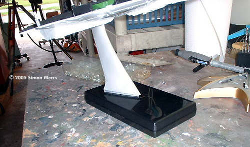
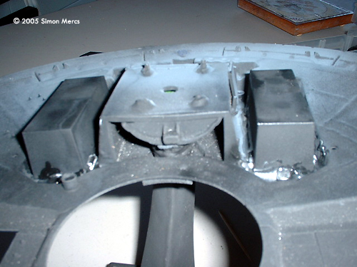
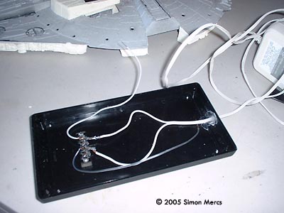
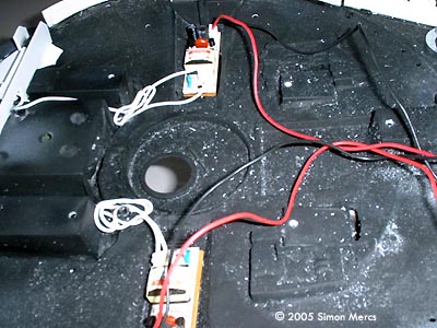
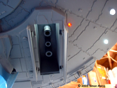
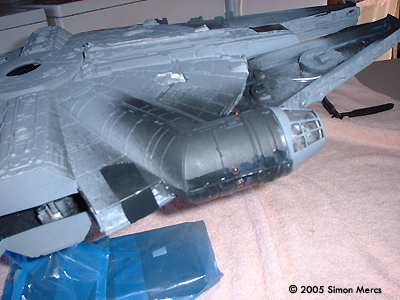
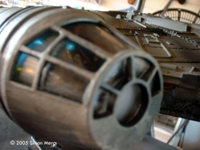
Image: First, the base is connected to a wall unit and leeds run to the model. |
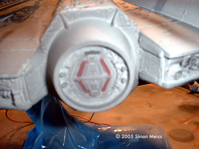
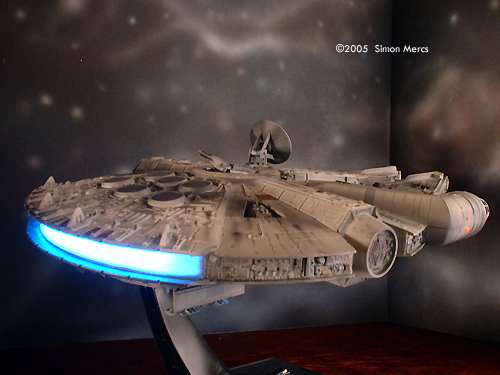
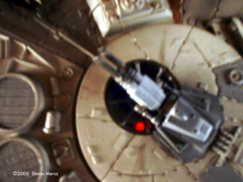
Day 11 Today I am concentrating on getting the engine lighting tested, installed, and completed. The "lightbox" structure was modified to allow the now slimmer craft to accommodate it. Careful positioning of the two CCFL tubes was needed to allow a good even dispersal of light to get that blue crescent just right. I also added some refractors (mirrors) to augment the light reflecting inside. The clear engine cover was frosted to get an even light seen outside, and not allow the spectator to see the inner workings and ruin the illusion. After several tests, the look seems correct and I am happy with the results. Notice the inverters found a good home in the recesses of the gangplank and the space docking coupler. There are also vents that are not obvious around the stand to allow heat from the inverters to escape. Time spent today: 9 hours |
|
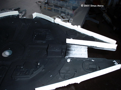
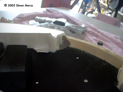
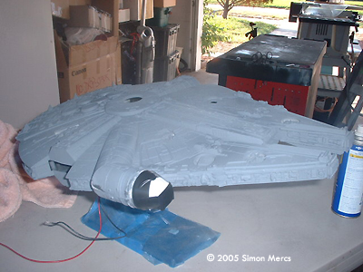
Image: ... like reinforcing this seam. |
Day 12 Today, I'm going through the model to find potential light leaks in seams and corners. This is a needed chore whenever you light up a model or prop, because it looks lousy if light leaks in small areas that are not blocked correctly. I use an epoxy compound that is wonderful for this purpose. It is found at most hardware stores and is used in various repairs. It also costs a fraction of what Hobby Stores charge for similar products. After that, the exterior was primed with a gray primer to allow good paint adhesion later. A blue masking frisket is used to protect the base from overspary. The base will be finished in a glossy black, and has already been primed. Time spent today, 4 hours. |
|
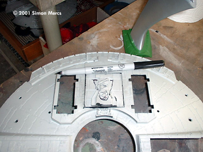
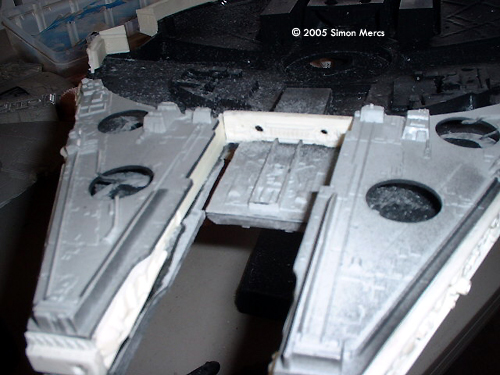
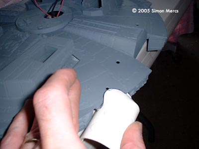
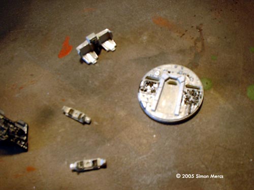
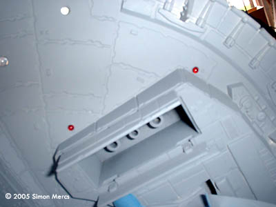
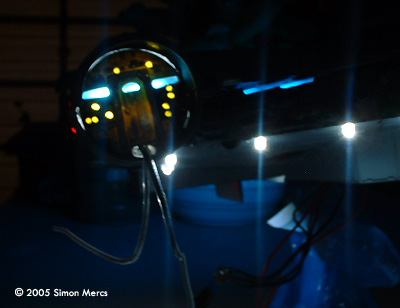
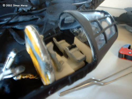
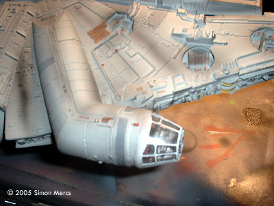
Image: Marking the position for the cockpit |
Day 13 I spent some time getting the cockpit installed correctly today. The location of the after-market cockpit bottom from Falcon Kits was marked then installed according to my best judgment based on the fit when the top cover is positioned. All seams and spaces were filled to make sure the part is unified into the main Hull section. The interior was also tackled and some detailing to the panels with very tiny instruments was done. I used reference pictures of the actual Millennium's cockpit to get the correct color scheme and instrumentation patterns. The forward instrument panel will be drilled out to allow several lights and blinkers to be installed. This will give a very nice effect to the viewer looking in through this section. As it is the only glimpse into the craft on the entire model, I strive to make it the best I can in the space allotted. The controls were painted silver to allow a lot of reflection of the colored gels that were installed in the spot where the lighting in the actual Falcon's cockpit are located. Notice I used a blue gel to get those linear fluorescents seen in the real prop's wall to come alive. Yellow gel was used to enhance the controls spread throughout the panel. All this will be lighted from behind by two ultra-bright LEDs. The cabin layout was accurized with the addition of the 2 highback chairs behind the pilot's chairs. Lastlty, the rear wall was painted in off-white, gray, and black. Time spent today: 9 hours. |
|
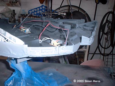
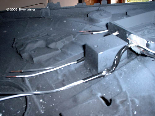
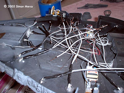
Image: Running wires |
Day 14 Today was a fun day for me as I love to light up a model! The pictures show the process of installing each LED in its correct position. There are a heck of a lot of lights in this one. The wiring will have to be tamed later as my goal today was merely to place each LED in the positions matched to the real prop in the initial survey I did before starting the build. The cockpit looks very cool upon being tested, and it should really add to the build's impression to the buyer. There are almost 50 LEDS in this build-up, and all have a purpose. The model is presented in a "Landing Descent" so the legs will be down, and all that glorious landing lighting will project down. All the connections will be done later and the main power line will be strung down through the opening I have created in the stand rod. This will lead to the power coupler in the base. This should be a very brightly lit mdel when completed. I am thinking of issuing a pair of sunglasses to the recipient. Time spent today: 8 hours. |
|
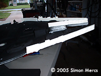
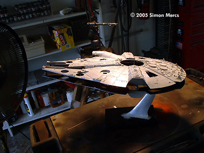
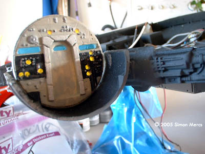
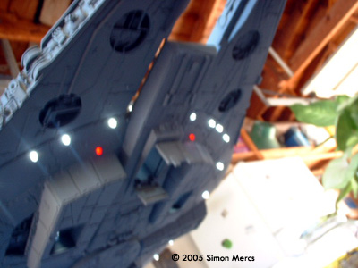
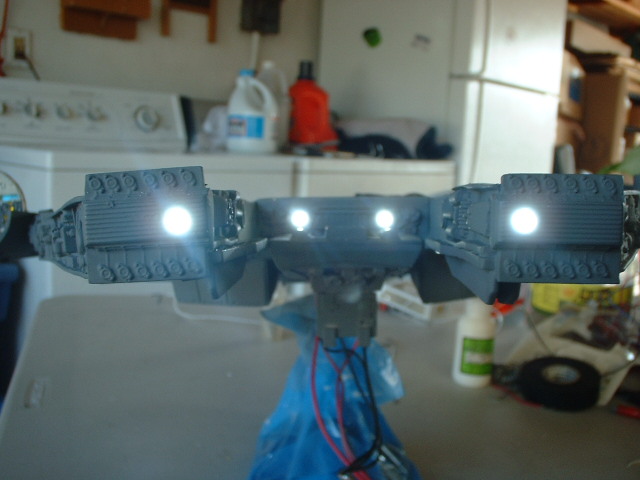
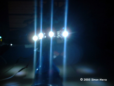
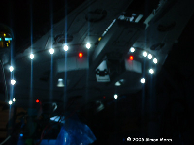
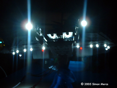
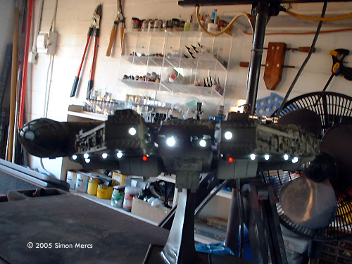
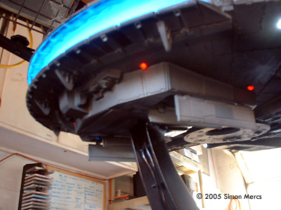
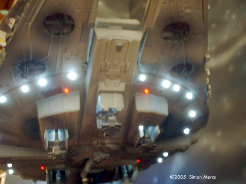
Image: Bright, even in daylight |
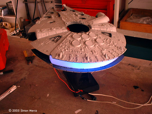
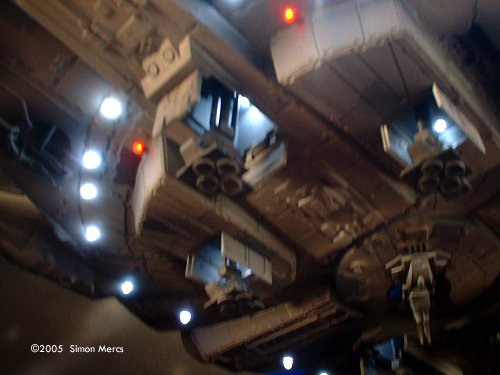
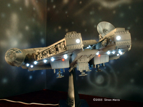
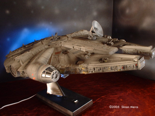
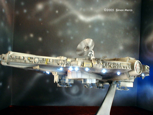
Day 15 Wow! Is the operative word of the day. Today I finished taming the electrical mess created yesterday. All leads were hooked up to their respective polarity and soldered for durability. All connections are then wrapped to prevent any potential short circuits from other wires in the assembly. The light tests were a blast, sooo bright! The idea of the model is that it's in its descent to landing, like in the scene when the Falcon was landing on the Cloud City pad - legs extended, all navigation lights on, cockpit aglow with instrumentation. The stand was angle to maximize this effect. As you can see from the darkroom shots, it's a very luminous display! The red and white navigation markers are located per prop reference pictures. The landing bays are also lit to enhance the detailed after-market landing gear that will be installed last. I let the system run for several hours so my neighbors could stare in amazement. No major heat build-up resulted and all systems are go. Time spent today: 7 hours. |
|
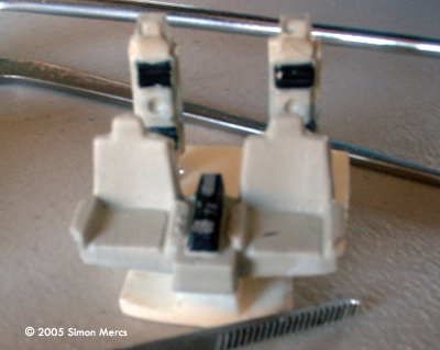
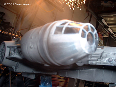
Image: Seating |
Day 16 The illuminated cockpit is the object of today's assembly. All interior sections and the flashing lighting were installed. The seats and figures of Han and Chewbacca were detailed and test fitted before I glued it all in. The forward command console was drilled out with a series of tiny apertures to allow the red and green flashers to give the illusion of a busy control center. Han was positioned in his agitated "I fixed that" position. The lighting tests show the effect looks realistic. The rear cabin wall was light blocked to prevent stray illumination seeping through the paintwork. This was a very delicate assembly and care was taken not to spoil the clear glass "windshield", as this is the only glimpse of the Falcon's interior details. Time spent today: 7 hours. |
|
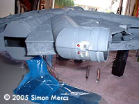
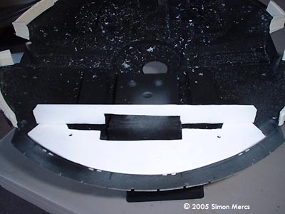
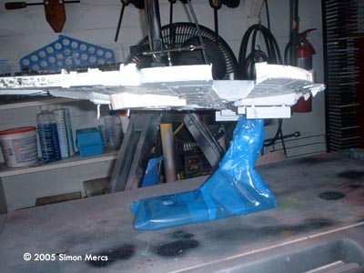
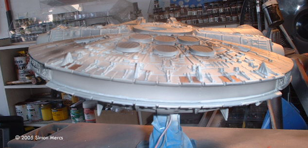
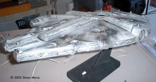
Image: Light blocking paint was applied to the seams |
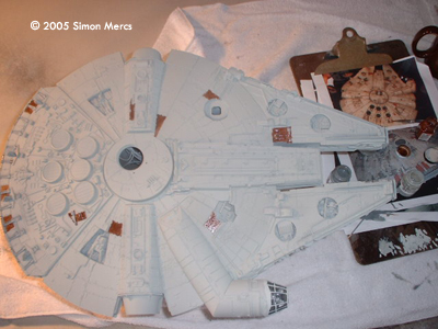
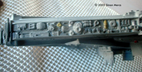
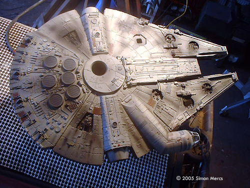
Day 17 The hull sections were joined today - finally! Once all seams and light leaks were checked out, I began to paint the primary color, a Flat Gull Grey. The clear engine part was masked with lo-tack frisket, and the cockpit was covered with the same part from another Falcon kit. Perfect fit! Two even coats of paint were applied to get a good foundation. Then I moved on to detail of tiles. There are numerous sections done in Medium Grey, Dark Gull Grey, and Rust/Red mix. These were applied while my trusty reference material is in full view. I used various shots of the real prop at the Smithsonian exhibit and stills from the newly released DVD set. This was a long process and a steady hand was needed. Once all the details were applied the model was placed under the hot lamps for a good drying session. Time spent today: 10 hours. |
|
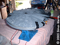
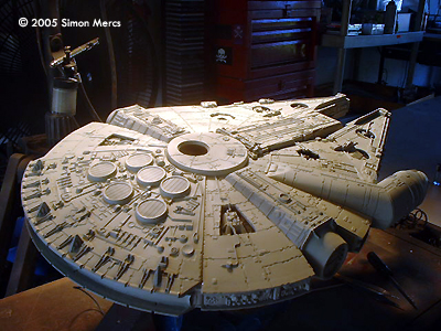
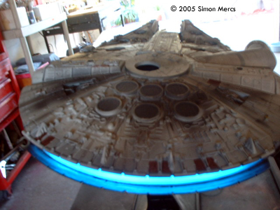
Image: Larger view of the above |
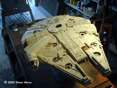
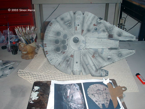
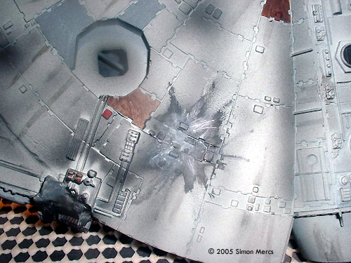
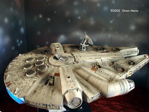
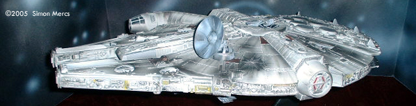
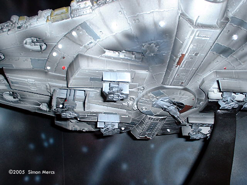
Day 18 Weathering! My favorite part after lighting. On a Star Wars model, it is absolutely essential to weather correctly. Using a "stippling" method, which is the application of texture by misting, I got a good rough look overall. Then I began to add streaks and other marks seen on the real prop. The difficult art is to be consistent and not too heavy. You still want to see the color underneath, but altered - not covered - by the weathering. It's taken me many years to do this with a certain confidence. Early weathering results by a novice can be a disaster and cause you to completely re-paint the mess you just created. I know this from experience. Go easy and light. Other than landing gear, gun turret details, and the radar dish, the kit's parts are all in place. Some final weathering will be done with a dry brush, and battle damage still needs to be applied. Time spent today: 7 hours. |
|
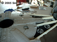
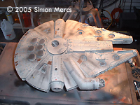
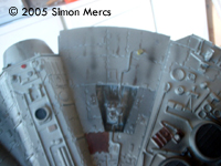
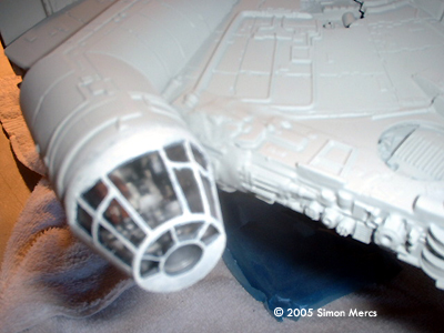
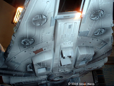
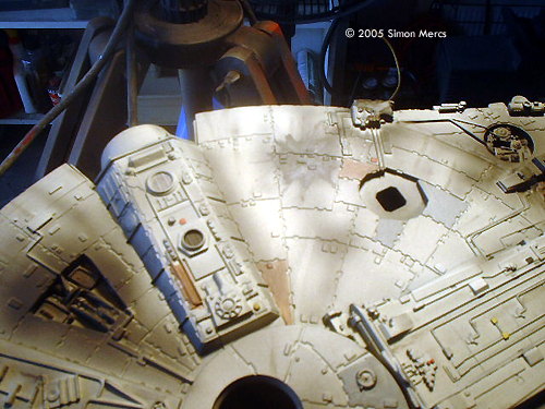
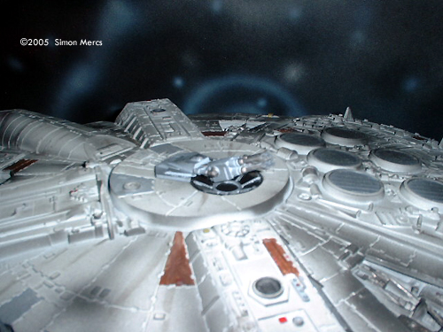
Image: Sidewall detail |
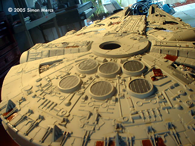
Day 19 Today I did some final weathering details. This required some darkening details in the side panel sections and battle scars as seen on the real prop. A lot of rust effects and streaks were also added to reinforce the "worn" look of the Falcon. I am very close to completion now - only a few parts are required to call this complete! Time spent today: 6 hours.
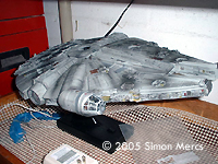
Image: Overall |
|
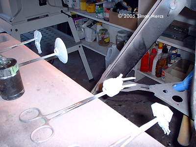
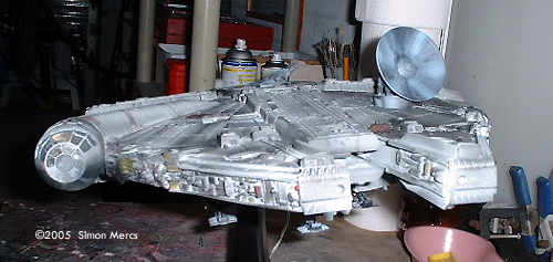
Image: Priming the fiddly bits |
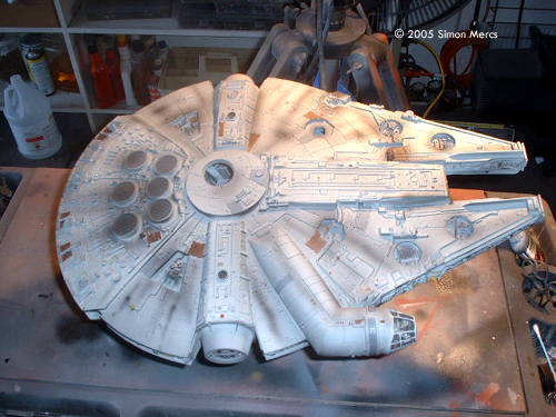
Day 20 Today I gathered the last of the parts to be assembled and started on the final stretch of this construction. The guns and radar dish were primed, painted, and finally detailed to match the rest of the model. The guns were given some charred metal colors on the barrels and mounts. The glass sections of the gun turrets were "smoked" to give the look of residue from constant gun battle discharges. The ribs were highlighted in Flat Gull Grey. The starboard and portside landing bay doors were also finished. These are fragile add-on parts, so I waited to the end to apply them. The "yellowish" stains and rust spots on the hull were some of the last weathering details applied. Again, all according to images of the real ILM prop. The only thing left is the actual accurized Landing Gear which has metal parts and is much more accurate than the provided parts in the ERTL kit. Time spent today: 7 hours. |
|
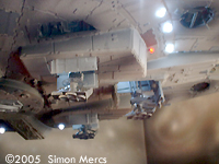
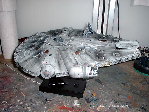
Image: Landing gear, from the front |
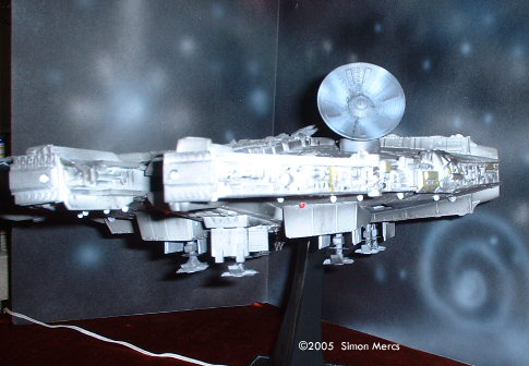
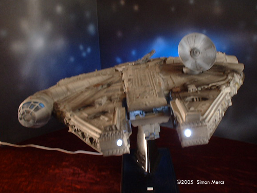
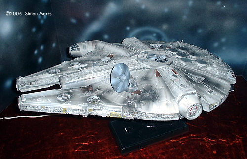
Day 21 I concentrated today on the landing gear and finalizing this model! Landing gear is the accurized version from Falcon Kits and it is a lot more precise in configuration than the ERTL pieces. I painted the pieces to fit in with the overall color scheme. Results are really nice and the deployed landing gear really brings this model to a higher plane. Once attached and all touch ups completed, I spent some time taking photographs of the results with a starfield background. Thanks for joining me on this long venture. In a Galaxy far far away this project is now history. Time spent today: 8 hours. |
![[The universe is a big place - and so is this site. Here's a map.]](http://www.starshipmodeler.com/resource/sm_sitemap.gif) |
| Visit our sponsors! | Advertise with us |
![]()
This page copyright © 2005 Starship Modeler™. Last updated on 8 June 2005.
![[Parts is parts]](sm_mf/mf01_2.JPG)
![[Parts is parts]](sm_mf/mf_07_01.JPG)