
|
The projects in this section are presented as step-by-step journals. Our intent is to delve deeper into the nuts and bolts of constructing and finishing a particular project while giving a sense of how long it takes. The subjects will range from simple kits to complex dioramas and everything in between. Authors will range in skill level, and include hobbyists and professionals. If you have a project you would like to share here, please drop us a line to discuss it. |
|
| USS Enterprise NCC-1701 |
|
![[Please click to enlarge]](mc_ent/01_IMGP2790.jpg) |
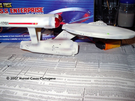
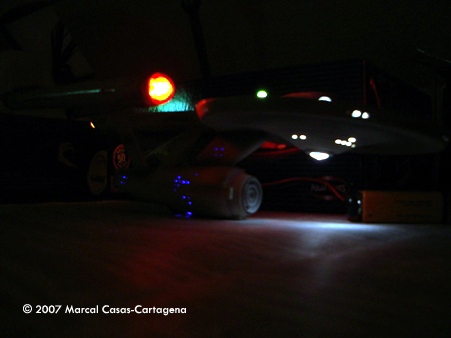
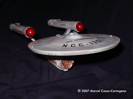
Project type: Mass Market kit with modification and lighting by Marcal Casas-Cartagena - images & text © 2007 This document shows my very first model kit for eight years. For the first time I used an airbrush and electronics. So this report could be helpful for people who, as well as me, is taking contact with this activity for the first time. I am a great fan of Star Trek so I chose the original Enterprise to star. The lighting will be spinning lights in the Bussard collectors, yellow light in the bottom of the nacelles, position blinking lights in the top of the saucer and inner light in the main and secondary hull. |
|
Done! |
|
|
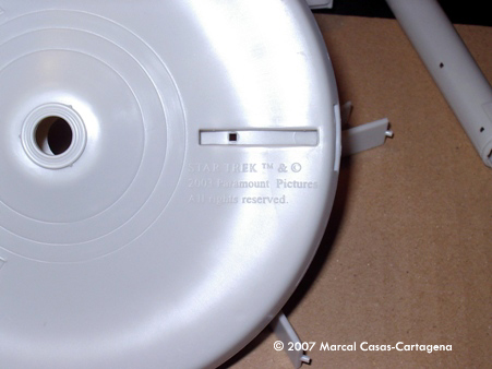
Image: Nice copyright from Polar Lights in a very hidden place. Do they think that people will be unable to remove that? |
Day 1 My kit has finally arrived. I bought it on eBay (the closest ScFi store is about 80 Km from my home) and it always takes a while. I have arrived home before my wife, so the first thing I do is tidy up the house, wash the dishes and so on. Now my conscience can relax and I can start working hard. With this kit is it possible to build three different ships, as everybody knows. I decided to build the one from the first season (round nacelles bottom, etc.), so the first thing I do is to separate the parts I am going to use from the rest. I have two nacelles types and that is great because with the pair I do not want I can do some practice for the electronics. After I detached the pieces I sand every stub from the plastic trees. The kit looks good, but a big copyright from Polar Lights must be removed from the bottom of the saucer. Tomorrow I am going to buy putty to smooth the pylons. To finish the day, I apply a coat of black paint as a light stopper inside the kit. Time spent today: about 8 hours |
|
|
|
|
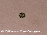
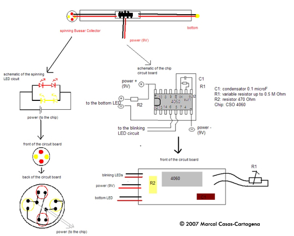
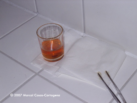
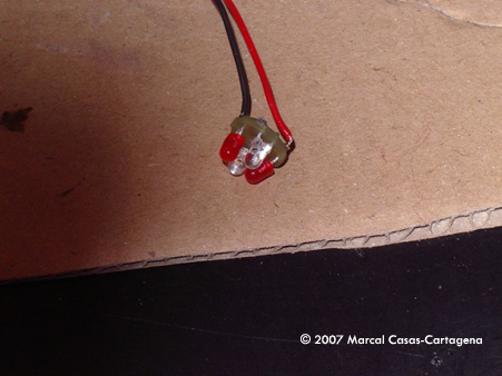
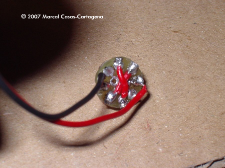
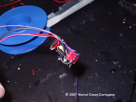
Image: Circuit schematics for the nacelles engines Image: FeCl3 solution. This solution is very soft. You can find FeCl3 everywhere so it is not a problem to work with it. |
Day 2 Today I arrived late from work and I am very tired. I decided to start the lighting of the nacelles. I want to attach a timer chip inside each nacelle. It will give a spinning effect to each of the Bussard collectors. In this collector there is place to add a round circuit board with 4 LEDs (3 mm), two red and two yellow, alternating. When connected to the chip (CSO 4060) they will blink consecutively, first the red ones and later the yellow ones. It will be possible to choose the blinking frequency via a variable resistor. The chip will be soldered to a circuit board. Using the same board it is possible to give light for a LED that I want to put in the bottom of the nacelles. I drew the circuit I designed on a virgin board (board with a layer of copper). The lines and dots must be done with a permanent marker (water resistant). After I cut off the round board I placed it in an Iron Chloride (III) solution. The iron (III) is an oxidant cation and it oxidizes the copper from the board from copper (0) to copper (II) cation, which is soluble in water. At the same time the iron (III) is reduced to iron (II). The process is known as Red-Ox reaction. |
|
All the copper from the board will react unless it is covered with the permanent marker. Chemistry is useful (sometimes). Today I have only done on of the round board circuits, tomorrow more. Editor's Note: CultTVMan.com sells pre-made LED/circuit boards designed to fit the PL kit nacelles, for those who would rather skip the better living through home chemistry. Time spent today: 1 hour. |
|
|
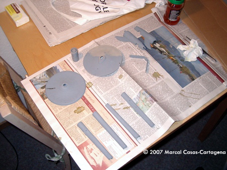
Image: The base coat is applied over all the surface of the ship. |
Day 3 Today it is an easy day. I finished the other round circuit board. On this one I was been able to draw the correct circuit onto the board. I fixed that doing some connections via cable. It is pretty difficult to do exactly the same thing twice... While the circuit was in the FeCl3 bath, the base coat was applied to the kit. After everything was ready, the LEDs were soldered to the circuit. I have a long experience in soldering and I still find the soldering paste very useful. It helps a lot when applied with a small brush on the surfaces to be soldered. Time spent today: 7 1/2 hours. |
|
|
|
|
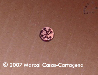
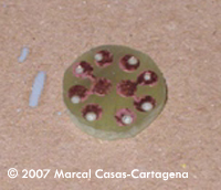
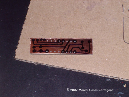
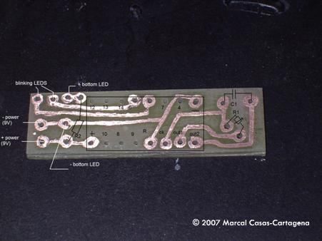
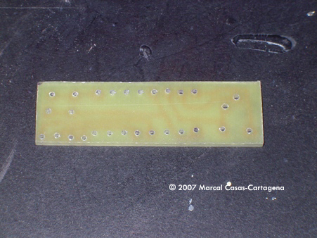
Image: Circuit board before removing the cupper layer. |
Day 4 More electronics for today. I drew the circuit board for the chip and other elements. I got the idea of using this chip from the article of Clyde Jones. I strongly recommend you read this article for a deeper understanding of this device. I followed the same procedure as yesterday and I still had time for soldering the components on the board and giving it a try... and it works!. In the Clyde's article he mentioned to use a 470 K Ohms resistor attached to the chip. With this resistor I did not find any good combination to simulate the spinning effect. So I changed this resistor to a variable one (up to 0.5 M Ohm); by varying the resistance it was possible to vary the frequency. I finally chose to attach the spinning LEDs to the pins 5 and 6 of the chip (the polarity does not matter, because it is switching between pins and therefore we have the spinning effect). For the frequency I chose a resistance of 66 K Ohm. Time spent today: 4 1/2 hours. |
|
|
|
|
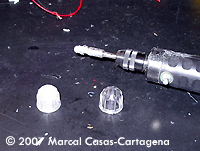
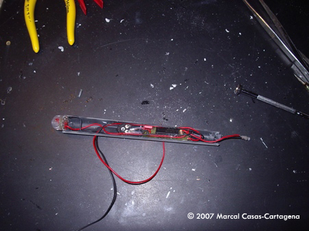
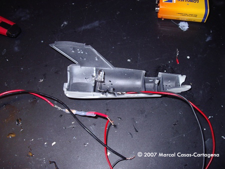
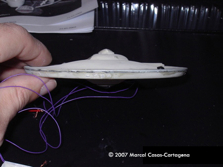
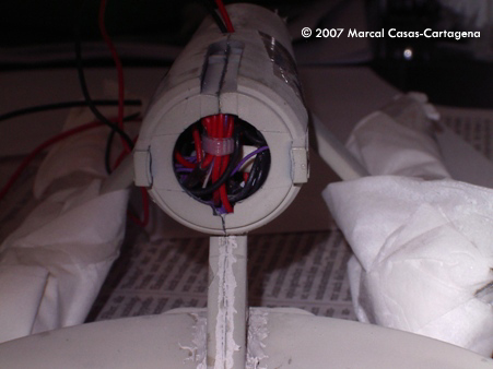
Image: Final fitting tests with the nacelles. For the first tests I used the additional parts of the kit once again. |
Day 5 Today I am going a fix the circuit inside the nacelles. Before I do so I want to make up a little bit the clear part, the Bussard collectors. These clear parts are really clear, very transparent. If I leave them that way we will see the LEDs from the outside, which will not look very nice. So I took a motor tool and sanded the clear part from inside. It made a diffuse effect that will look much better. After this was done, I made several attempts to fix the board inside the nacelle. Of course it did not fit at once and the motor tool was used again to make the board a bit smaller. It was also necessary to remove some snap pins from both halves of the nacelles. I was a bit afraid to do so, but it is important to remember that this kit will be glued as usual, whether or not it was intended to be a snap-fit. After much work everything fits. After a test to see if the pylons still fit and to draw where the channels for the power wires will be placed I went to sleep. Time spent today: 7 hours. |
|
|
|
|
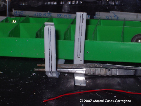
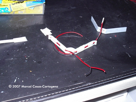
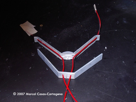
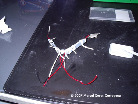
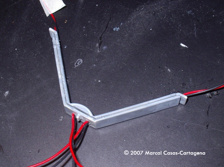
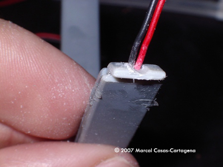
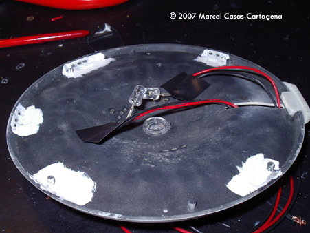
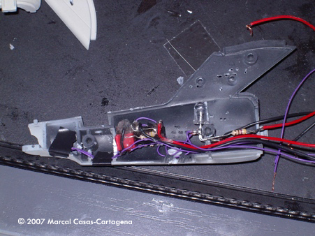
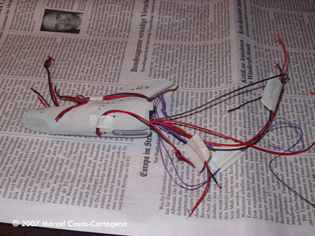
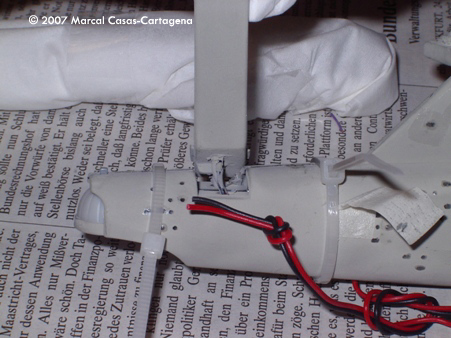
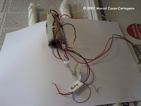
Image: Wires are on their guides and the chemistry makes its work. |
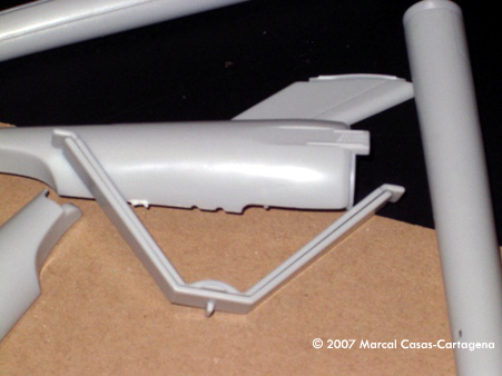
Day 6 I started removing the material of the warp nacelle pylons to do the guides. The only wire available in my usual electronic store is 1 mm thick, so the guides must be relatively deep. And so I make them so. The wires were fixed to the V with epoxy glue and when it becomes more or less dry the two V halves were also glued. I let it dry. Later on putty was applied to smooth the seams between parts. The next step is to fix the pylons and the nacelles together. This is supposed to be done when both halves of the nacelles are already fixed, but in my case I fixed the corresponding half of the nacelle and then I fixed the other half. In this way I can glue the pylon and the nacelle for the inner side and the bond becomes much stronger. After this I let it everything set up overnight. Time spent today: 5 hours. |
|
|
|
|
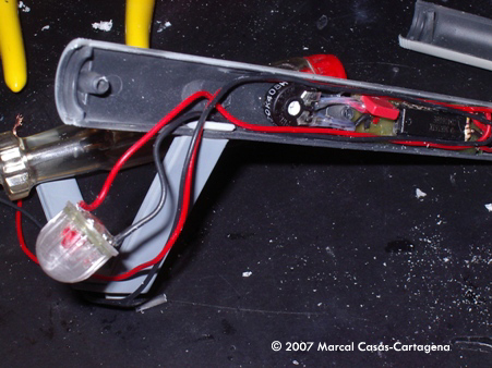
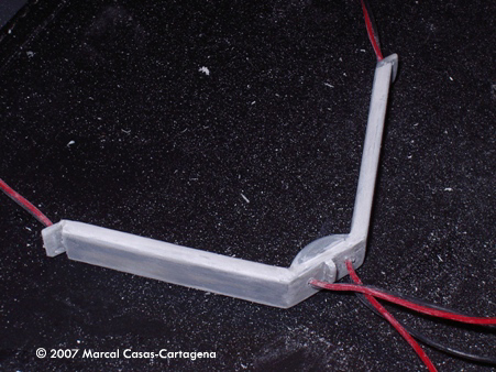
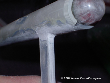
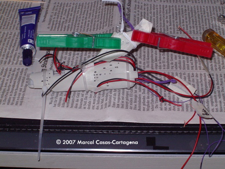
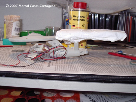
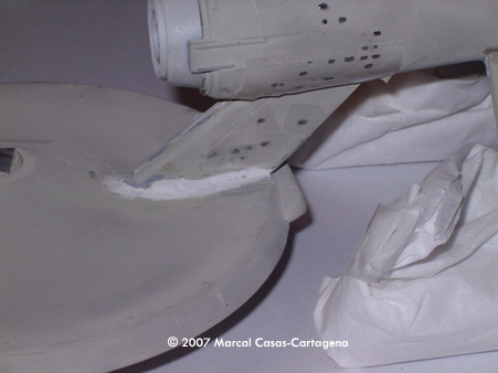
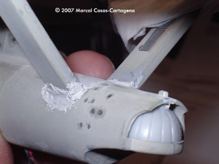
Image: Putty time! |
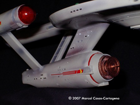
Day 7 Today I am going to finish the nacelles. I removed the pressure devices and everything remains in its place, so now it is putty time. I applied putty everywhere: at the bottom, the connections between parts, etc. When it had cured, I sanded it smooth. Finally the Bussard collectors were painted in clear red. The most important thing: the lighting still works. Time spent today: 4 hours |
|
|
|
|
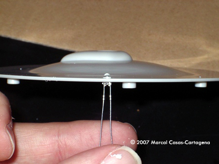
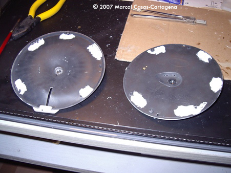
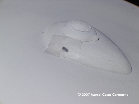
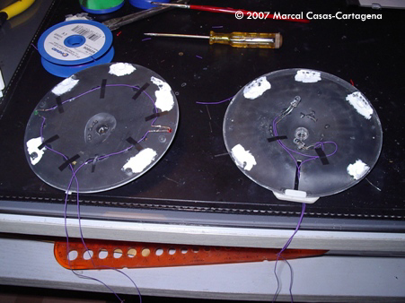
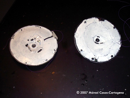
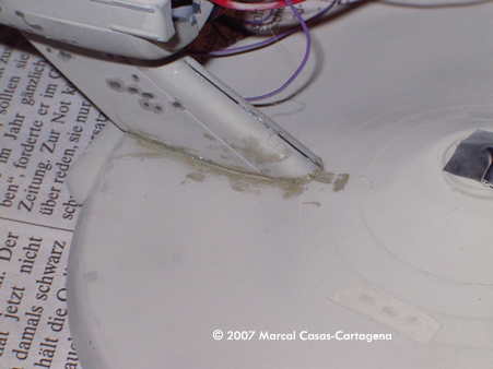
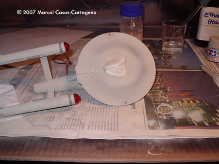
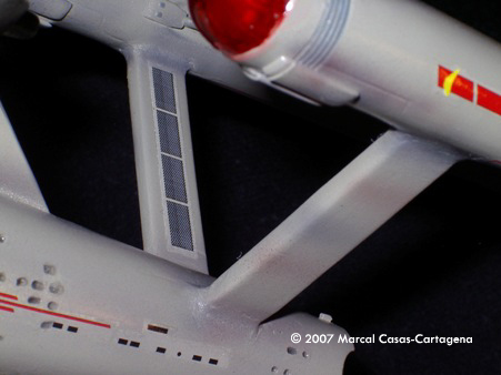
Image: White layer where the yellow LEDs are supposed to be fixed. |
Day 8 It is time to start with the main hull (saucer). My idea is to light it up with two white 5 mm LEDs in the middle and one yellow 3 mm LED in each window on the edge of the hull. Step by step I drilled the windows in both saucers and applied white paint where the yellow LEDs are going to be. White color reflects light very well and black color, on the other hand, absorbs it. So with a bit of white paint the lighting is supposed to be more effectively spread around. I do not know why but I spent lot of time today, with not a lot to show for it. Time spent today: 8 hours. |
|
|
|
|
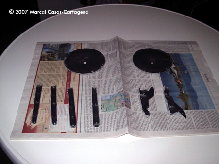
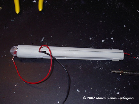
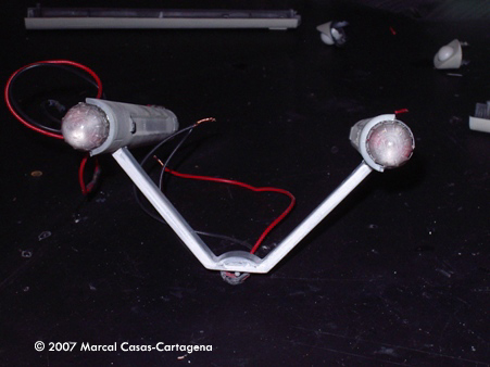
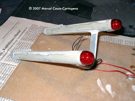
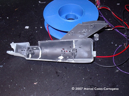
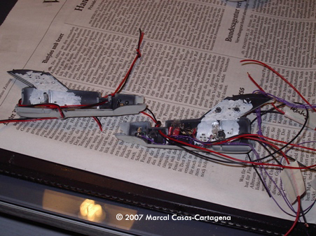
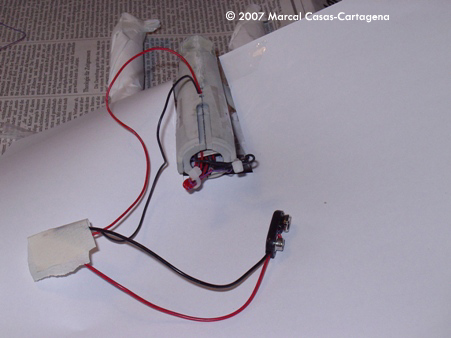
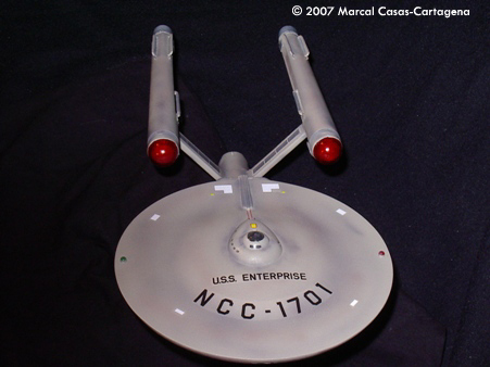
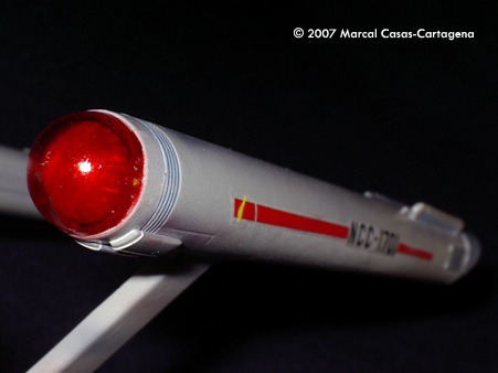
Image: Nacelles ready from the back. |
Day 9 I do not know why, but I made the wrong decision to paint and apply decals to the nacelles. The only problem in this decision is that later on I will have to protect them when the final painting is to be done. Live and learn. When the nacelles were ready I painted the saucer (both halves). When it was dry I put tape in the windows and filled them with epoxy resin from the inside. After the resin dried I got very nice and transparent windows. I continued with the lighting. I tried several combinations and finally I decided not to use the yellow LEDs because the hull is not thick enough and even if I drill the hull a little bit the both halves do not fit correctly. So I added a layer of white on the entire inner surface to spread light from the other LEDs around. The blinking LEDs, green to the right and red to the left, were attached in their holes. I left long wires to connect them inside the secondary hull. Finally I glued both halves of the saucer and fixed with tape to keep them together overnight. Time spent today: 10 hours. |
|
|
|
|
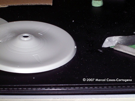
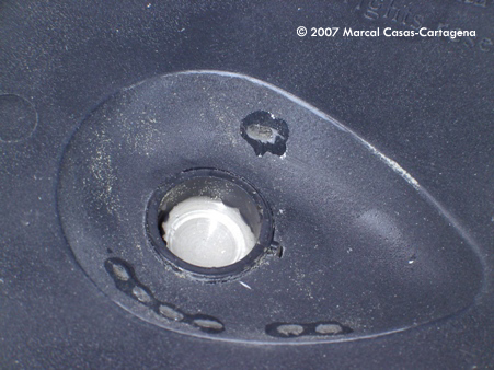
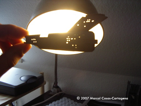
Image: Windows already drilled. |
Day 10 Today is going to be a long day. I started to do a similar process for the windows in the secondary hull as I did in the main hull. But then I remembered that I have extra stickers (and additional option with the kit, useful in the case that the builder does not like decals) I can use the to mark where the windows will be. The windows process was otherwise completed as before. When I finished with that I prepared the chip for the position lights in the main hull. I did it without circuit board to save some room and I used a 470 K Ohm resistor instead a variable one. The chip was fixed inside the secondary hull. Then, one 5 mm blue LED was fixed in the secondary hull, connected in parallel to a 3 mm blue LED in the bottom of the ship, close to the shuttle bay. When I was sure that everything still worked I sanded the main hull. The next step was to fix all the wires in the secondary hull and proceed to glue the main hull to the neck. For the nacelle's power cables I arranged a wire from the bottom of the ship to the deflection dish hole. Later on I will solder these wires with the nacelle ones and then push them to the deflector dish hole. I did the same thing for the cables for the main hull. When all the mess of cables was more or less organized I glued the two halves of the secondary hull. After a couple of hours the saucer section was fixed with the neck. All the cable ends were in the deflector dish hole for the final connection. The cables for the main power supply are not missing; they will go out to the vessel in the same place as the stand is suppose to be. The nacelle cables were soldered, after which step-by-step the wires were stuffed inside the vessel and pulled out the hole.Now is the critical moment. When I tried to fix the nacelles to the ship I realized that I fixed the nacelles in the opposite direction. So if I fix the 'V' as it should be, then the Bussard collectors are right in the rear of the ship. Drat! When I explained it to my wife she could not help herself but started laughing and, in the moments I am writing these lines (4 days since the accident), she is still laughing. And she is right; I was foolish not to check it twice or three times. What can I do now? I glued as well as I could and tomorrow I will sand it and so on. Time spent today: 11 hours. |
|
|
|
|
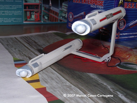
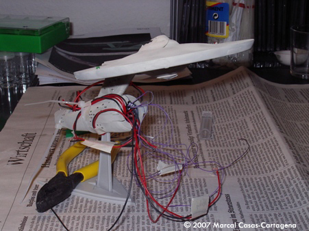
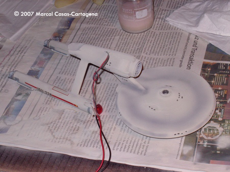
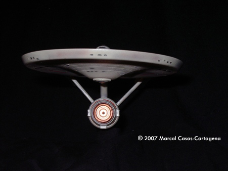
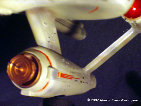
Image: I believe that the problem does not affect the general design. |
Day 11 I believe that my sacrifice was successful. The warp nacelle pylon problems have been solved. Today is a putty day. I apply putty everywhere to make smooth connections between parts. Unfortunately I will have to paint all the ship again and so I have a problem with the windows. But it could be worse… The final wire connection has been done and the cables have been hide inside the hull. Everything fits. Time spent today: 9 hours. |
|
|
|
|
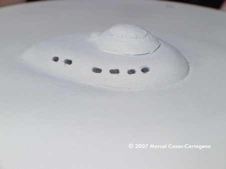
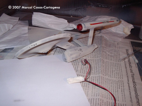
Image: Weathering begins |
Day 12 Today is finally painting day. To solve the windows problem I drilled the windows again. When the paint was dry I applied the epoxy resin very carefully. The result does not look bad. Finally, a little bit of so-called weathering is applied to give a realistic look to the model and later on the decals. It is the very first time that I used and airbrush so I am a bit afraid to mess up all the model. The result is not been bad at all. Only the gloss coat is left. Time spent today: 6 hours |
|
|
|
|
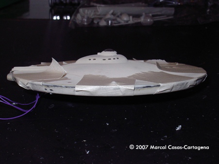
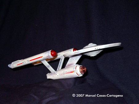
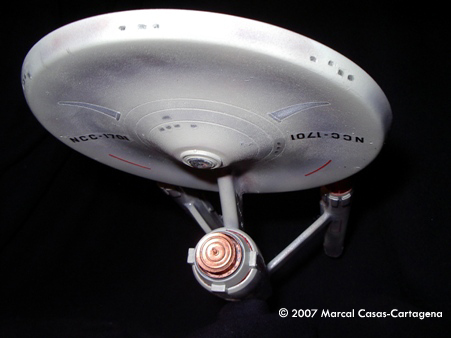
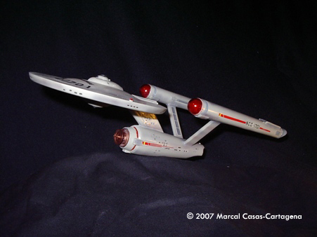
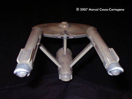
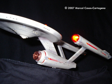
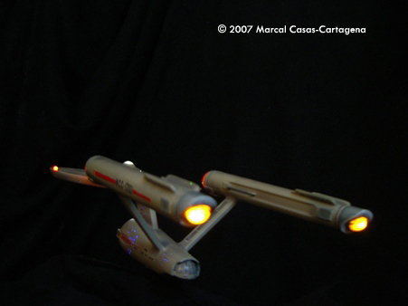
Image: Starboard side |
Day 13 Today is easy. Only some clear coat and to take some pictures. Only a nice stand is left, but I will do it next week. Conclusion If I had to do this kit again there are some things I would like to do different: I would use fiber optics for all the windows. I would do the windows at the end directly. I would also use directly the correct normal resistors for the chips in the nacelles (my electronic store is far away and not a fun drive). The chip for the position lights would be inside the saucer - or even better I would try to control all the blinking LEDs with only one chip. I had a lot of fun with this kit and I am looking fordward for the Enterprise 1701-A from Polar Lights. It has been useful to get in touch with the modeling again and try and airbrush for the first time. I do strongly recommend this kid to everyone, beginners and advanced builders. Have fun with it! |
|
|
|
![[[Star Trek models & more at the Starship Modeler Store]]](http://www.starshipmodeler.com/resource/trek_ad_1.jpg) |
| Visit our sponsors! | Advertise with us |
![]()
This page copyright © 2007 Starship Modeler™. Last updated on 19 March 2007.
![[Please click to enlarge]](mc_ent/ent-01-01.jpg)
![[Please click to enlarge]](mc_ent/ent-04-04.jpg)
![[Please click to enlarge]](mc_ent/ent-06-01.jpg)
![[Please click to enbiggen]](mc_ent/ent-07-01.jpg)
![[Please click to enlarge]](mc_ent/ent-08-01.jpg)
![[Please click to enlarge]](mc_ent/ent-09-01.jpg)
![[Please click to enlarge]](mc_ent/ent-10-01.jpg)
![[Please click to enlarge]](mc_ent/ent-11-01.jpg)
![[Please click to enlarge]](mc_ent/ent-12-01.jpg)
![[Please clicck to enlarge]](mc_ent/ent_13_IMGP2759_Retocada.jpg)